This chapter covers the following topics:
• [Protecting the control plane with QoS](https://learning.oreilly.com/library/view/building-resilient-ip/1587052156/ch04.html#ch04sec1lev1)
• [Protecting applications with QoS](https://learning.oreilly.com/library/view/building-resilient-ip/1587052156/ch04.html#ch04sec1lev2)
• [Building blocks of QoS](https://learning.oreilly.com/library/view/building-resilient-ip/1587052156/ch04.html#ch04sec1lev3)
• [Application QoS and control-plane traffic](https://learning.oreilly.com/library/view/building-resilient-ip/1587052156/ch04.html#ch04sec1lev4)
• [QoS deployment strategy](https://learning.oreilly.com/library/view/building-resilient-ip/1587052156/ch04.html#ch04sec1lev5)
---
This chapter examines how quality of service (QoS) can be deployed to assist in building a resilient IP network. QoS refers to the ability of a network to enforce preferential treatment to applications, through a series of classification, policing, congestion avoidance, and queuing. Although QoS is not directly responsible for ensuring that the network is up and running all the time, it has a direct impact on the resiliency of the network.
It is important to remember that resilient networks must fulfill two requirements:
• Maintain high availability
• Ensure consistent user experience
The first requirement aims to keep the network running as long as possible and to recover from failures in an efficient and transparent manner. Two types of problems can adversely effect the availability of network:
• Physical failure
• Control-plane failure
Whereas redundant components and routing protocols are used to prevent physical failure, QoS can be used to prevent control-plane failure.
As stated in [Chapter 2](https://learning.oreilly.com/library/view/building-resilient-ip/1587052156/ch02.html#ch02), “[Establishing a High-Availability Network](https://learning.oreilly.com/library/view/building-resilient-ip/1587052156/ch02.html#ch02),” it is the user’s experience that matters. Users consider the network at fault when their applications suffer from performance or quality of delivery. This is another area where QoS comes in to help fulfill the second requirement of a resilient IP network.
### Protecting the Control Plane with QoS
As discussed in [Chapter 3](https://learning.oreilly.com/library/view/building-resilient-ip/1587052156/ch03.html#ch03), “[Fundamentals of IP Resilient Networks](https://learning.oreilly.com/library/view/building-resilient-ip/1587052156/ch03.html#ch03),” the control plane ensures the overall health of the router and its ability to forward traffic. A heavily loaded control plane is bad for the router, because the router might lose its ability to track changes in the network, recover from faults quickly, or, in the worst case, it might completely break down. The control plane of a router may be kept busy for many reasons. Some are intentional, such as a denial-of-service (DoS) attack, whereas some are inherent in the implementation of protocols.
Protecting the control plane is an important component of building a resilient network. A good understanding of the types of traffic that affect the control plane is crucial. In addition, knowing how different features can be used to protect the control plane is useful.
#### Traffic Types That Affect the Control Plane
One of the basic roles of a router is to forward packets from one interface to another. Packets that are not meant for the router itself but that require forwarding are called _transit packets_. Through the improvements made to the various switching technologies, routers can handle transit packets without the intervention of the CPU. In many situations, however, the service of the CPU is required:
• [Process switching](https://learning.oreilly.com/library/view/building-resilient-ip/1587052156/ch03.html#ch03sec2lev11)
• Transit packets with IP option
• Transit packets with Time-To-Live = 1
• Packets destined for the router (for example, ping)
• Management packets for the router (for example, Simple Network Management Protocol (SNMP) or Telnet)
• Routing protocol packets (for example, Open Shortest Path First (OSPF) and Border Gateway Protocol (BGP))
• Broadcast traffic
• Address Resolution Protocol (ARP)
• Layer 2 keepalives
• Traffic that needs fragmentation
Whenever a router receives packets that fall into the preceding list, its CPU has to be interrupted to process these packets. The rate at which these packets arrive at the router has a profound impact on the overall well-being of the router. In an extreme case, the rate of arrival can be so high that the router is so overwhelmed with the traffic that it cannot maintain the rest of the processes properly. When this happens, performance of the router suffers and the following can occur:
• The router cannot keep up with Layer 2 keepalive messages, which causes its peer to think that it has gone down.
• The router loses its Layer 3 keepalive messages, which causes its routing protocol peer to think that it has gone down.
• The router has a problem learning new routes (for example, processing new BGP updates).
• The router’s routing table is not kept current.
When any of these things happen, the availability of the network is affected. Therefore, a control-plane failure is a serious problem and should be avoided.
Many features have been implanted in the Cisco IOS Software to protect the CPU of the router from overloading. The aim is to protect the CPU so that the router can function properly under all traffic conditions. Because the router receives all sorts of traffic that requires the attention of the CPU, the aim is to be able to prioritize and choose which traffic to process first. This is when QoS plays an important role.
For QoS to work, the various traffic must be sorted first. After that, you can prioritize traffic for the CPU to process. It is also necessary to choose what sort of traffic to process in the first place. After prioritizing the traffic, you want to have the additional ability to dictate at what rate the traffic should be processed.
#### Tagging Routing Protocol and Layer 2 Control Packets
Of all the packets that need the CPU’s attention, the most important ones come from the routing protocols and the Layer 2 keepalives. These two categories of traffic are the most important, because losing routing protocol updates means having an invalid routing table, and losing Layer 2 keepalives may be misinterpreted as a link down.
To differentiate these packets from the rest, they have to be tagged so that they can be recognized and given priority for processing. There are two ways to tag these packets, depending on whether the router is sending packets out to a peer or whether the packet is to be used internally:
• [IP Precedence](https://learning.oreilly.com/library/view/building-resilient-ip/1587052156/ch04.html#ch04sec3lev1)
• [The pak_priority flag](https://learning.oreilly.com/library/view/building-resilient-ip/1587052156/ch04.html#ch04sec3lev2)
##### IP Precedence
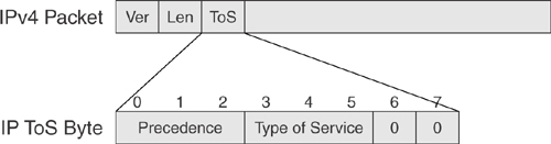
The IP Precedence is used for tagging when routing protocol messages are sent to external peers by the router. As illustrated in [Figure 4-1](https://learning.oreilly.com/library/view/building-resilient-ip/1587052156/ch04.html#ch04fig01), the IP Precedence is made up of the first 3 bits within the Type of Service (ToS) byte of the IP packet.
**Figure 4-1** _IP Precedence_
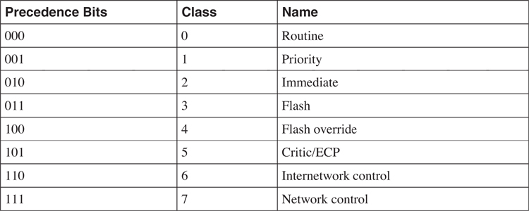
Depending on the setting of its 3 bits, the IP Precedence provides eight classifications, as illustrated in [Table 4-1](https://learning.oreilly.com/library/view/building-resilient-ip/1587052156/ch04.html#ch04tab01).
**Table 4-1** _Original Meaning of the Precedence Bits_
When sending out routing protocol updates, a router tags all the packets with an IP Precedence set to 6. This is enabled by default and does not need configuration. The following routing protocols use this feature:
• Routing Information Protocol (RIP)
• OSPF
• BGP
##### The pak_priority Flag
Whereas the IP Precedence is used when the router sends out routing protocol packets, the pak_priority is for use by Cisco routers internally. When a packet arrives at the interface of a router, the interface driver queues the packet with a packet header. The packet header indicates the type of information that has arrived. The pak_priority is a flag within the packet header that Cisco IOS Software uses to prioritize the treatment of this packet within the router.
Whereas the IP Precedence affects how external parties treat the packet, the pak_priority affects how packets are queued within the router. The tagging of these two fields is independent, and both might not be used by applications running within the router. For example, when a router sends out packets originating from OSPF, the IP Precedence is set to 6 with pak_priority turned on. However, only IP Precedence is set to 6 for BGP packets.
Besides IP routing protocols, the pak_priority is also used by other non-IP protocols and Layer 2 keepalives. The following are some of these protocols:
• RIP
• OSPF
• Intermediate System to Intermediate System (IS-IS)
• Point-to-Point Protocol (PPP)
• High-Level Data Link Control (HDLC)
• Asynchronous Transfer Mode (ATM)
• Frame Relay
• Spanning Tree Protocol (STP)
Through the use of IP Precedence and pak_priority, the router can differentiate high-priority control packets from normal traffic that is bound for the CPU. This capability is important for it to implement the next phase of control-plane protection, which is selective packet discard (SPD).
#### Selective Packet Discard
SPD is the ability of the router to give priority to the processing of the routing protocol packets. The routing protocol packets are given higher priority over other packets to reach the input queue of the CPU. This is to ensure that the router can maintain the integrity of its forwarding tables and its states first before processing other packets.
With SPD, traffic sent to the CPU is sorted, and checks are performed to decide whether to drop or to continue processing the traffic. Two queues are allocated for the sorting of the traffic: a general queue and a priority queue. Packets put into the priority queue are processed first regardless of other traffic conditions. Packets put in the priority queue include routing protocol packets or those with IP Precedence set to 6. The general queue is for holding packets from some other applications that also need the CPU’s attention. In this case, the traffic might still be subjected to checks, and so a chance still exists that the traffic might be dropped. When the queue size of the general queue is in between a minimum and maximum threshold, packets are dropped randomly. These drops are called _SPD flushes_.
With SPD, the router does what is critical to its well-being: The router processes the most important messages from the routing protocol and Layer 2 keepalives first. By ensuring that its most precious resource is protected, the router can then maintain proper states and continue to forward traffic.
#### Receive ACL
Although SPD gives priority to the routing protocol traffic and Layer 2 keepalives, it is more important to ensure that the traffic destined for the CPU is indeed legitimate in the first place.
The receive access control list (RACL) complements the protection of the CPU by enforcing an external net of defense around it. RACL is implemented at the ingress interface of the router and is activated after the input ACL. Traffic destined for the router is subjected to the RACL, and depending on its configuration might be dropped even before the SPD is activated. RACL is useful in DoS attack prevention, because the router can be configured to respond only to queries from certain hosts and reject all other traffic.
The RACL works just like a normal ACL. [Example 4-1](https://learning.oreilly.com/library/view/building-resilient-ip/1587052156/ch04.html#ch04ex01) shows a sample that allows only ping and OSPF packets to be sent to the router.
**Example 4-1** _Configuring RACL_
---
ip receive access-list 100
access-list 100 permit icmp any any echo
access-list 100 permit ospf any any precedence internet
access-list 100 deny ip any any
---
With SPD and RACL in place, the CPU of the router might still become overwhelmed (for example, when a DoS attack is launched at the router with the flooding of ping packets at the router). In [Example 4-1](https://learning.oreilly.com/library/view/building-resilient-ip/1587052156/ch04.html#ch04ex01), the RACL permits ping packets to the router. Because ping packets are allowed to pass through the RACL and fit the requirement to be processed by the CPU, precious CPU resources are spent on processing these packets. Under a DoS attack, the CPU can be crippled with this traffic. The control-plane policing (CPP) tightens the protection of the CPU, as you learn in the next section.
#### Control-Plane Policing
The CPP further tightens the protection of the CPU by applying the usual QoS mechanism of matching and policing on packets bound for the CPU. The Modular QoS command-line interface (CLI) (MQC) is used in this case to define the policy.
In CPP, the CPU is treated just as another host within the router where MQC can be applied to its ingress and egress interfaces. Ingress is for traffic bound for the CPU, whereas egress is for traffic originating from the CPU. Although CPP adopts the nomenclature of MQC, certain restrictions apply to the use of certain MQC features:
• The only actions allowed are police and drop.
• Matching is based on standard and extended ACLs, IP Differentiated Services Code Point (DSCP), and IP Precedence.
Because CPP can be configured via the MQC, you have flexibility in terms of defining different traffic types bound for the CPU with different treatment characteristics. [Example 4-2](https://learning.oreilly.com/library/view/building-resilient-ip/1587052156/ch04.html#ch04ex02) shows how to configure CPP to give priority to BGP and OSPF traffic, while policing on the management traffic and other IP traffic.
**Example 4-2** _Configuring CPP_
---
access-list 100 permit tcp any any eq bgp
access-list 100 permit ospf any any precedence internet
access-list 101 permit icmp any any echo
access-list 101 permit tcp any any eq telnet
access-list 101 permit udp any any eq snmp
access-list 102 permit ip any any
class-map routing_traffic
match access-group 100
class-map management_traffic
match access-group 101
class-map normal
match access-group 102
policy-map cpp
class management_traffic
police 128000 1500 1500 conform-action transmit exceed-action drop
class normal
police 64000 1500 1500 conform-action transmit exceed-action drop
control-plane
service-policy input cpp
---
### Protecting Applications with QoS
Protecting applications with QoS is the second requirement that a resilient network needs to fulfill. The previous sections in this chapter have described how you can deploy QoS to protect the control plane. Now, the following sections describe ways to ensure consistent user experience, especially in a converged IP network.
#### Understanding the Need for Application QoS
The concept of QoS has been around for quite some time. One topic of discussion among network managers has always been whether QoS is necessary in the first place. The most common misconception has been “throwing bandwidth at the problem.” The reason for this misconception has been the mix-up between solving a capacity problem as opposed to solving a QoS problem.
In the past, many applications had their own dedicated network. Think of a bank, in the past, for example. The bank had at least a dedicated phone network to provide for voice service, an SNA network to run its banking applications, a separate network that provided for videoconferencing service, and maybe even a separate network for video surveillance. Each of these networks was running different protocols and different networking technologies. Voice was running on a time division multiplexing (TDM)-based network, while the SNA network had an automatic teller machine that connected to the network via 64-kbps leased lines. The videoconferencing solution was most likely running on ISDN, and the surveillance was on a proprietary technology. Collectively, these myriad of networks made up the communication infrastructure of the bank. Because each of these networks carried a single application, the only way to improve performance was via upgrades of hardware and bandwidth. To enable more calls to be made from a branch, the TDM connection had to be upgraded. To support new-generation automatic teller machines, the 64-kbps line had to be upgraded to 128 kbps. This kind of network conditioned network managers to think that upgrading bandwidth is the only way to solve a problem.
Today, the same bank has a totally new communication infrastructure consisting of a converged IP network: a single network that carries with it voice service that is based on VoIP, banking applications that are web based, videoconferencing that is done via IP-based software, and a video surveillance system that has IP-enabled cameras. “Throwing bandwidth” seems to continue to solve some of the problems, but it has come to a point where it is either too expensive to continue doing so, or it does not work anymore.
The reasons why this is so can be attributed to a few factors:
• [Latency](https://learning.oreilly.com/library/view/building-resilient-ip/1587052156/ch04.html#ch04sec3lev3)
• [Jitter](https://learning.oreilly.com/library/view/building-resilient-ip/1587052156/ch04.html#ch04sec3lev4)
• [Loss](https://learning.oreilly.com/library/view/building-resilient-ip/1587052156/ch04.html#ch04sec3lev5)
These factors might not be relevant in the communication infrastructure of the past, but they become apparent in a converged network infrastructure. The following sections describe these factors and the effects they have on the applications.
##### Latency
In an IP network, latency is defined as the time taken for a packet to enter and leave the network. As shown in [Figure 4-2](https://learning.oreilly.com/library/view/building-resilient-ip/1587052156/ch04.html#ch04fig02), packet A enters the network at time = t0 and leaves the network at time = t1. The latency of the network, t2, for packet A, in this case, is t1 − t0.
**Figure 4-2** _Network Latency_
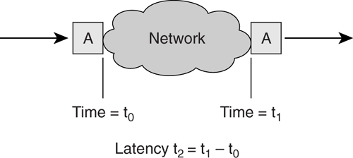
Note that latency is an end-to-end measurement of network delay. The time, t2, is the total delay introduced from various components of the network. These include transmission technology used, the speed at which packets can be forwarded at each intermediate node, and the various transmission speeds along the way.
Many network managers think that latency problems can be solved by adding bandwidth. This is not true, as can be illustrated in a simple example. Suppose that two towns, A and B, are connected by a single-lane highway that permits only a speed of 10 miles per hour. These towns are 100 miles apart. And suppose there is a car with two people who need to travel from town A to town B. It will take them 10 hours to reach town B. Now suppose the highway has been expanded to a two-lane highway. Each of the two people can now take two cars to go from town A to town B. They can even invite one more person each. But they will still take 10 hours, because the speed limit is still 10 miles per hour. Although the capacity of the highway has increased, the time taken to reach town B is still the same. The effect of adding bandwidth is like adding an extra lane to the highway. Because bandwidth solves only the capacity issue, it does not solve the latency problem.
Latency becomes a big issue in a converged network, because applications such as voice and video have stringent requirements regarding latency. For example, VoIP applications, such as the one used by the bank, generally require a one-way delay of 150 ms. A breach of this requirement might result in problems such as echo and incomprehensible conversation. Problems such as this, something that is audible, are apparent to users and totally unacceptable to them. The 150-ms requirement contrasts with having to wait 5 seconds for a file transfer to complete. With the introduction of each node or link within the network, latency adds up. The introduction of other applications on the same network that contend for the same resources might also increase the latency.
##### Jitter
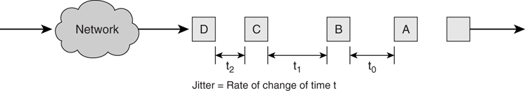
Another factor that is closely related to latency is jitter. Jitter is defined as the rate of change in the time gap between consecutive packets. As shown in [Figure 4-3](https://learning.oreilly.com/library/view/building-resilient-ip/1587052156/ch04.html#ch04fig03), the time gap between packets A and B, t0, might be different from that between packets B and C, t1, after traversing through the network.
**Figure 4-3** _Network Jitter_
Just like latency, jitter is another key requirement for delivering good-quality voice or video applications. Consider video applications, for example. If the jitter is negligible, the image is delivered in a smooth manner to the end user. On the other hand, with high jitter, the video suffers from jerky images and, in the worst-case scenario, might not be visible at all.
Jitter is affected by the traffic condition in the network. As a video packet traverses the network, it has to contend with packets from other applications along the way (for example, FTP and web applications). The latter two applications have a very different characteristic from that of the video: They are bursty by nature and may transmit variable-sized packets. The network needs to ensure that the jitter for the voice and video is not affected by these applications. This is when QoS is required.
##### Loss
Besides solving latency and jitter issues, preventing packet loss in applications such as voice and video is critical. Although losing one packet once every great while might not adversely effect these applications, losing too many might produce undesirable results. A long silence might interrupt a conversation, or a video screen might appear blank. In the case of the bank doing surveillance using an IP camera, losing images might have serious consequences.
Packet loss also results from the traffic condition in the network. A converged network carries different application types of data, video, and voice. These different applications must contend for the resources in the network. If the network is congested, packets are dropped because no resources are available. The network must be able to prevent the loss of packets that belong to voice and video applications. This is an area QoS can help in mitigating the risk of packet loss.
#### Determining When to Deploy QoS
With an understanding of the need for QoS to combat latency, jitter, and loss, it is also important to know when to deploy QoS. Many times, this is mixed up with the need to provision additional bandwidth. Sometimes you need only one of them to solve a problem, whereas at other times you might need both.
A few scenarios will help you decide when QoS is needed and when adding bandwidth will help within a network.
##### Scenario 1: Undercongested Link
The left side of [Figure 4-4](https://learning.oreilly.com/library/view/building-resilient-ip/1587052156/ch04.html#ch04fig04) shows that because the traffic load over a period of time is always less than the peak bandwidth, there is no congestion at all on the link.
**Figure 4-4** _Scenario 1_
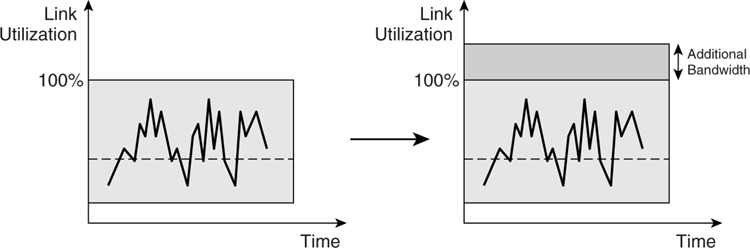
Because there is no congestion at all in this scenario, adding bandwidth does not contribute anything at all (as shown on the right side of [Figure 4-4](https://learning.oreilly.com/library/view/building-resilient-ip/1587052156/ch04.html#ch04fig04)). No benefit derives from deploying QoS to prevent packet loss either. The only reason to deploy QoS is to tackle the latency and jitter issues, if they exist. One key consideration here is the link speed in this scenario. If it is a low-speed link, jitter becomes an issue if packets from a voice application have to be transported across the link behind other applications with large packets. For high-speed links, this problem might not be an issue at all. In this scenario, it is recommended that for link speed of 768 kbps or below that QoS be considered to meet the latency and jitter requirements.
##### Scenario 2: Occasionally Congested Link
The left side of [Figure 4-5](https://learning.oreilly.com/library/view/building-resilient-ip/1587052156/ch04.html#ch04fig05) shows the case when a link is occasionally congested. The right side shows when additional bandwidth was introduced just to cater to the spikes of traffic load that happened every once in a while.
**Figure 4-5** _Scenario 2_
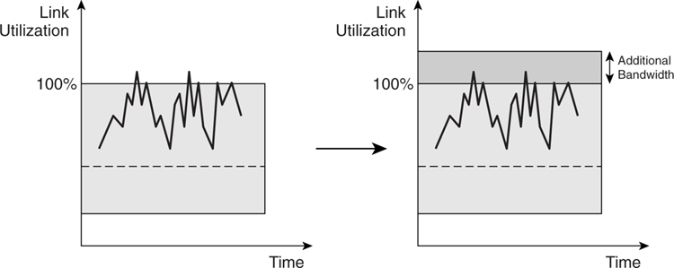
In this case, it might be too expensive to deploy the additional bandwidth in response to occasional spikes. This is when the benefits of QoS are most apparent. The occasional spikes are called _transient congestion_. They only happen occasionally, such as when month-end reports need to be churned out for reporting purposes. QoS is most effective in solving transient congestion because it eliminates the need for additional bandwidth, thus achieving cost-savings. This savings is most obvious when you are dealing with expensive WAN links. Multiply the cost of the WAN links a hundredfold for a bank, for example, and the savings can be quite substantial.
Another reason to deploy QoS in this case is to prevent loss of packets belonging to voice or video applications during period of transient congestion. You can achieve this via prioritization of the traffic and selectively dropping other traffic. The requirement for latency and jitter will be the same as that described in scenario 1.
##### Scenario 3: Badly Congested Link
[Figure 4-6](https://learning.oreilly.com/library/view/building-resilient-ip/1587052156/ch04.html#ch04fig06) shows a case when the traffic load is more than the original bandwidth most of time. This is a classic case of a capacity issue, and the addition of bandwidth is absolutely required. Without adding bandwidth, attempting to deploy QoS as in scenario 2 is not going to help much, because the traffic load just overwhelms the available bandwidth. This is also a classic case when QoS is being tasked to solve the wrong problem. It might be able to help some applications, but overall, too many applications are affected and the overall effect of the QoS implementation does not help.
**Figure 4-6** _Scenario 3_
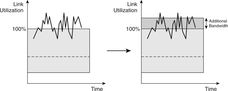
In this scenario, introduction of more bandwidth is absolutely necessary to solve the capacity issue. If adding bandwidth brings the situation to that of the first scenario, then preventing loss packets via QoS will not be necessary. However, QoS will still be required to solve the latency and jitter issues, just as in scenario 2.
### Building Blocks of QoS
The Differentiated Services (DiffServ) model is the building block for QoS applications. DiffServ, defined in RFC 2475, is one of the two QoS architectures for IP networks defined by the IETF. It works on a provisioned QoS model and does not require the application to signal for reservation of network resources.
In the DiffServ model, the network attempts to segregate traffic into different classes based on the DSCP field in the IP packet. Based on the individual class, network nodes within the network then perform the following activities:
• [Classification and marking](https://learning.oreilly.com/library/view/building-resilient-ip/1587052156/ch04.html#ch04sec2lev8)
• [Congestion avoidance](https://learning.oreilly.com/library/view/building-resilient-ip/1587052156/ch04.html#ch04sec2lev9)
• [Congestion management](https://learning.oreilly.com/library/view/building-resilient-ip/1587052156/ch04.html#ch04sec2lev10)
• [Traffic conditioning](https://learning.oreilly.com/library/view/building-resilient-ip/1587052156/ch04.html#ch04sec2lev11)
#### Classification and Marking
Traffic classification is the most fundamental step that needs to be taken when deploying DiffServ model QoS. It is the action of separating different applications so that priority or special treatment can be accorded to them. Without traffic classification, all applications will look the same within the network, and all will be treated the same, which defeats the purpose of QoS. After the traffic classification has been done, there has to be a way to identify the traffic from different applications, which is where traffic marking, sometimes referred to as _coloring_, comes in. Traffic marking identifies these different applications by setting the ToS byte in every packet of the application; subsequent action can then be taken by the devices in the downstream direction.
Classification and marking should be done at ingress of the network so that time-sensitive applications can be recognized early and preferential treatment can be given.
#### Congestion Avoidance
Congestion avoidance is a QoS strategy that monitors network traffic in an effort to anticipate and avoid congestion before more severe problems occur. The concept of congestion avoidance is tightly linked to TCP’s behavior under network overload situations. As discussed in [Chapter 3](https://learning.oreilly.com/library/view/building-resilient-ip/1587052156/ch03.html#ch03), “[Fundamentals of IP Resilient Networks](https://learning.oreilly.com/library/view/building-resilient-ip/1587052156/ch03.html#ch03),” TCP can ensure a reliable transmission of data. The strength of the TCP protocol lies in its retransmission function and its capability to regulate traffic flow. However, this very strength also makes TCP susceptible to a phenomenon called the _global synchronization_. Global synchronization happens because different TCP flows tend to adjust their window sizes at the same time, in response to network congestion.
Global synchronization causes inefficient use of bandwidth and increases latency and jitter in the network. The solution to global synchronization lies in exploiting the retransmission characteristics of TCP via the deployment of feature called random early detect (RED). The purpose of RED is to address congestion in an active manner rather than in a reactive manner. It is a mechanism whereby an IP gateway can infer an impending congestion by calculating its average output queue size. The gateway then goes on to drop certain packets randomly or mark the packets to indicate probability of a drop. By relying on the sliding window mechanism of the TCP protocol, RED solves the problem of global synchronization by preventing different TCP sessions from adjusting their window size at the same time. An enhancement to RED is weighted RED (WRED), which enables you to separate traffic into different classes, each with different dropping rates.
As the network speed gets higher, the concept of RED is especially important to keep the network throughput high while maintaining a low delay. This throughput is important for applications such as voice and video. However, to ensure consistent delivery of voice and video applications, it is critical that they not be subjected to congestion avoidance. Regardless of the underlying protocols used, random dropping of packets from these applications should be prohibited.
#### Congestion Management
Congestion management is also known as queuing. All the packets that arrived at a router have to contend for the scarce resource of the output buffer for transmission. The management of the use of the buffers is important. Over the years, different queuing methods have been introduced, including the following:
• First-in, first out (FIFO)
• Priority queuing
• Custom queuing
• Weighted fair queuing (WFQ)
• Class-based weighted fair queuing (CBWFQ)
• Low-latency queuing (LLQ)
Choosing a right queuing strategy is critical to delivering the service that is expected of each application. In a converged network, to overcome the latency and jitter demand of delay-sensitive applications, LLQ is recommended for this class of application. The rest of the bandwidth is then shared by the rest of the applications via the CBWFQ.
#### Traffic Conditioning
Traffic conditioning is perhaps the easiest concept of all QoS tools to understand. Basically, the network avoids potential trouble by limiting the amount of traffic that an application can send at any one time. This limit can be achieved in either of two ways: via traffic policing or via traffic shaping.
Traffic policing enables you to manage traffic by specifying an allowable transmission rate and what action to be taken for excess traffic. The action to take is either dropping the traffic or marking the traffic with lower precedence. On the other hand, traffic shaping buffers the excess traffic and tries to smooth the flow by delaying the sending of the excess traffic.
Applications such as voice and video should not be subjected to shaping because this has the effect of increasing latency and jitter. However, the use of the policing function on this class of traffic may be considered as a safety measure to ensure that they transmit within the bandwidth allocated.
For more details about QoS and its building blocks, refer to _End-to-End QoS Network Design: Quality of Service in LANs, WANs, and VPNs_ by Tim Szigeti and Christina Hattingh (Cisco Press, 2005).
### Application QoS and Control-Plane Traffic
In the section “[IP Precedence](https://learning.oreilly.com/library/view/building-resilient-ip/1587052156/ch04.html#ch04sec3lev1),” you learned that a router makes use of the IP Precedence to tag the packets when sending out routing protocol messages. The IP Precedence is also used by routers to tag traffic of other applications. Therefore, it is important to understand how the router behaves when it also has QoS enabled for the applications in the network.
When it comes to classification and marking, IP routing protocol messages are tagged with IP Precedence of 6 before they are sent out by the router. This tagging has a significant impact on how the QoS should be designed. For one, no other applications should be using IP Precedence 6 or 7. Otherwise, packets from these applications might be confused with routing protocol updates, jeopardizing the control-plane stability. In fact, any traffic, other than routing protocol updates, with a IP Precedence of 6 and above should be disallowed to enter the network, or its IP Precedence reset to a lower level (a common practice for service providers). Likewise, it is also critical to ensure that when sending normal traffic to other external networks, the packets not be tagged with IP Precedence 6.
When it comes to congestion management, it is also important to understand how the router handles the routing protocol updates as well as Layer 2 control packets in its queuing. In distributed platforms such as the Cisco 7500 series, the packets with pak_priority set are placed in the default class if no separate QoS configuration is done. In this case, it has to share the queue with other applications, although its pak_priority setting ensures that it will not be dropped. For such platforms, it might be advisable to explicitly configure a separate class for the routing protocols and specify its own bandwidth requirement. Doing so will guarantee bandwidth availability for the updates and ensure consistent performance. Other Cisco routers, such as the 7200 and the lower-end series, deploy a totally different approach to handling these high-priority packets. Special queues are dedicated to processing these packets, and other queues are reserved for user-specified QoS configuration.
For the rest of the QoS tools, congestion avoidance and traffic conditioning should not be applied to the routing protocol messages at all. In fact, packets with a pak_priority flag set are never dropped by QoS implementations such as RED.
Understanding the way high-priority control packets are handled is crucial to maintaining a resilient network. Consider this fact when planning a QoS deployment strategy.
### QoS Deployment Strategy
Much can be said about the development of the QoS architecture and technology within the IP world. However, the percentage of networks deploying an end-to-end QoS architecture is still low. As mentioned in the beginning of this chapter, part of the reason could be because throwing bandwidth is still practiced by many network managers. Another possibility is that network managers try deploying QoS, but no visible benefits derive from the deployment. Many times, QoS deployment in a network fails mainly because of a lack of strategy. Without a proper strategy, just turning on some fancy QoS features will not work (and in a worst-case scenario, might break the network).
As part of the effort in building a resilient IP network, a proper QoS architecture is mandatory. And that means a proper documentation that deals solely on the QoS matters. One way to ascertain whether a network is well run is to ask for a QoS architecture documentation. Chances are, you will not find many.
The QoS deployment strategy should be worked out during the network design phase. It encompasses five major steps, as follows:
**Step 1** [Classify applications](https://learning.oreilly.com/library/view/building-resilient-ip/1587052156/ch04.html#ch04sec2lev12).
**Step 2** [Define policies](https://learning.oreilly.com/library/view/building-resilient-ip/1587052156/ch04.html#ch04sec2lev13).
**Step 3** [Test policies](https://learning.oreilly.com/library/view/building-resilient-ip/1587052156/ch04.html#ch04sec2lev14).
**Step 4** [Implement QoS features](https://learning.oreilly.com/library/view/building-resilient-ip/1587052156/ch04.html#ch04sec2lev15).
**Step 5** [Monitor](https://learning.oreilly.com/library/view/building-resilient-ip/1587052156/ch04.html#ch04sec2lev16).
#### Classifying Applications
The first step in the QoS deployment strategy is to identify all applications running within your network. You need to find out each application’s ranking within the business organization, and determine whether it is mission critical. You also need to understand the nature of each of the applications in terms of behavior, protocol, bandwidth requirements, and network characteristics. This is perhaps the most difficult part of all because ranking an application might involve politics within the organization, and many parties might be involved in this exercise. For example, a networking person might not know the application as well as the application person or the developer. In this case, trying to find out network requirements might require the involvement of other departments.
A good way to start is to understand the different traffic classes. Put simply, you can group all IP applications under one of these classes.
[Table 4-2](https://learning.oreilly.com/library/view/building-resilient-ip/1587052156/ch04.html#ch04tab02) shows an example of how applications can fall into one of these classes.
**Table 4-2** _Application Classes and Their Properties_
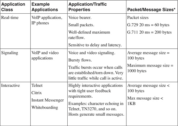
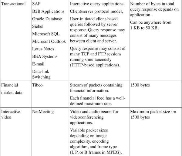
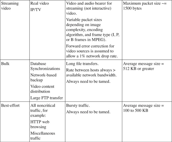
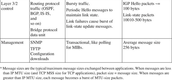
Based on the characteristics of the traffic, you now have a good understanding of how each of these applications behaves. Most important, there is a way to help decide which traffic type gets assigned to a certain IP Precedence or DSCP class. With information such as packet size and protocol setup, you can select the correct queuing mechanism to support the workings of the applications.
#### Defining Policies
After categorizing the applications, you can define the class of service for the QoS architecture. You will now have a good indication of the number of classes in the network, as well as the nature of the traffic flow. You can define policies with respect to the identified classes of traffic.
During policy definition, make sure you have logical and physical network diagrams. The logical diagram indicates the traffic flow within each class of traffic. The physical diagram reveals the bandwidth capacity, as well as potential bandwidth choke points within the network. With these important characteristics clearly identified, you can define the type of policies on each node. For example, the first-hop nodes are called the edge of the network. This is the place to perform classification and marking. Queuing and LFI are most often found in the WAN links with low-speed connections. As the traffic flows toward the core of the network, it is mainly WRED and queuing that play a more critical role.
#### Testing Policies
Testing is the system verification exercise for the QoS architecture. It is recommended that this be done in a test lab first rather than in a live environment. The test-lab phase of the entire testing exercise verifies the individual configuration. It also gives you an indication of the behavior of the router with the necessary features turned on. For example, you would want to make sure that router performance is unhindered. For hardware assist features, you would want to make sure that the required features are not through the CPU of the router.
After this initial test-lab phase, you can move the testing phase to a small portion of the network (to verify the effects of the QoS architecture on a small controlled number of applications or users). Before the actual QoS features are turned on, you must take a snapshot of the condition of the network during peak and nonpeak hours. For example, the snapshot can include a typical response time of certain transactions, quality of voice calls, time taken for certain data transfers to be completed, and so on. Then, after the QoS features have been turned on, you need to record the same parameters again to ascertain the effect of the QoS features on the same applications or users.
#### Implementing QoS Features
After the testing phase comes the implementation phase, when the QoS features have to be turned on in most of the network. A good practice is to always implement the QoS policy in a controlled manner and incremental fashion. The classification and marking have to be done first. This means the implementation phase starts from the edge of the network and moves toward the core. During this phase, updating of documentation is of utmost importance, because the network is undergoing changes. Proper documentation also allows for rollback to be carried out in the event that the new configuration does not perform to expectations.
#### Monitoring
The monitoring phase starts right after the policies have been implemented. The focus of this phase is on data collection and answering questions such as whether the QoS architecture is working.
You have two sources for data collection regarding QoS features:
• Management Information Base (MIB)
• IP Service Level Agreement (IP SLA)
The Class-Based QoS MIB stores vital information that can tell you lots of details about the QoS implementation. For example, information such as the number of packets marked or dropped can be accessed. This information gives a good indication of the traffic load of the network, as well as how the network nodes are reacting to the situation.
The other great tool for monitoring the effects of the QoS architecture is the IP SLA, formally known as the Service Assurance Agent (SAA). IP SLA enables you to monitor key network parameters such as delay, jitter, and the health of important network resources. IP SLA is discussed in detail in [Chapter 10](https://learning.oreilly.com/library/view/building-resilient-ip/1587052156/ch10.html#ch10), “[Beyond Implementation](https://learning.oreilly.com/library/view/building-resilient-ip/1587052156/ch10.html#ch10).”
The use of the Class-Based QoS MIB and the IP SLA give you a good indication of whether the QoS architecture is sound. In addition, as described in [Chapter 2](https://learning.oreilly.com/library/view/building-resilient-ip/1587052156/ch02.html#ch02), during scheduled network maintenance you might want to verify that you have implemented the QoS strategy successfully. You can do so by using test equipment to generate a load on the network and verifying that the voice traffic is not affected or unimportant traffic is being dropped during congestion. However, the ultimate tool that will tell you whether the QoS features are working is the end users. Remember, there is no point configuring a complex queuing mechanism with the latest QoS features when the users still find that their application is not working. Therefore, besides collecting network statistics, user visits are mandatory to gather feedback.
### Summary
Deployment of QoS is required in building a resilient IP network. It is needed in the areas of protection of the control plane, as well as ensuring consistent user experience. QoS is not an afterthought, and its implementation requires proper planning and should be done during the design phase of the network.