[Skip to Content](https://learning.oreilly.com/library/view/building-resilient-ip/1587052156/ch07.html#main)
[](https://learning.oreilly.com/home/)
- Explore Skills
- Start Learning
- Featured
[Answers](https://learning.oreilly.com/answers2/)
Search for books, courses, events, and more
## Chapter 7. Internet Module
---
This chapter covers the following topics:
• [Understanding Addressing and Routing in the Internet Module](https://learning.oreilly.com/library/view/building-resilient-ip/1587052156/ch07.html#ch07sec1lev1)
• [Establishing Internet Module Redundancy](https://learning.oreilly.com/library/view/building-resilient-ip/1587052156/ch07.html#ch07sec1lev2)
• [Implementing Security Measures](https://learning.oreilly.com/library/view/building-resilient-ip/1587052156/ch07.html#ch07sec1lev3)
• [Resilient Border Gateway Protocol (BGP) Design](https://learning.oreilly.com/library/view/building-resilient-ip/1587052156/ch07.html#ch07sec1lev4)
• [Using Network Address Translation (NAT)](https://learning.oreilly.com/library/view/building-resilient-ip/1587052156/ch07.html#ch07sec1lev5)
---
The Internet module is the building block that connects a corporate network to the Internet. With increased reliance on the Internet for connectivity purposes, the Internet module design has also undergone changes with respect to redundancy and security to support business continuity. The security aspect has been under the spotlight because of the emergence of denial-of-service (DoS) attacks on critical business websites.
Regardless of your network requirement and design, connectivity to the Internet requires you to understand some basic rules. These rules govern how the Internet is operated, and they also influence how the service providers provision their services. Some of these rules can be found in the technical documentation within the Internet community, such as those listed in [Table 7-1](https://learning.oreilly.com/library/view/building-resilient-ip/1587052156/ch07.html#ch07tab01). This documentation is an essential read because it will help you develop a strategy for a resilient Internet module design. Another good source of reference is _Cisco ISP Essentials_, by Barry Raveendran Greene and Philip Smith (Cisco Press, 2002).
**Table 7-1** _“Must-Read” RFCs_

Given that the Internet module is responsible for the entire network’s connection to the outside world, it is important that its design be well thought out. Although the best practices, such as a modular design concept, still hold, a few areas are most critical to the needs of the Internet module. These areas are important because they have implication on the overall resiliency of the Internet module. There is also a cost implication because connecting to the Internet involves paying a service provider for a service. The three major areas of concern in the Internet module design are as follows:
• Addressing and routing
• Redundancy
• Security
In addition to addressing these concerns, developing a resilient Internet module takes more than just redundant links. The routing of traffic for Internet access can be quite difficult and different from that of the internal network. For one, Internet routing requires different protocols and may involve cooperation from other parties, such as the service providers. In addition, special features are sometimes needed to overcome problems such as shortages of public IP address.
Internet module design involves careful planning and strategizing so that a certain level of resiliency can be achieved. The Border Routing Protocol (BGP) plays a vital role in the routing aspect. Depending on the addressing strategy and network design, another technology, Network Address Translation (NAT), also plays an important role. This chapter examines how the enhancements made to both BGP and NAT help in maintaining a highly resilient Internet module.
### Understanding Addressing and Routing in the Internet Module
Addressing and routing are closely related when it comes to designing the Internet module. For connectivity to the Internet, you need to know the various addressing practices adopted by the service providers. In addition, you need to have a thorough understanding of various concepts such as public and private addresses and classless interdomain routing (CIDR).
You can build a good foundation on the topics of addressing and routing for the Internet module from the various RFCs that have been published, some of which are known as Best Current Practices (BCPs). The RFCs cover topics such as address allocation guidelines, rationale for adopting certain addressing schemes, and routing best practices. [Table 7-1](https://learning.oreilly.com/library/view/building-resilient-ip/1587052156/ch07.html#ch07tab01) lists some “must-read” RFCs if you are designing the Internet module.
It is important that you are familiar with these RFCs, especially if you are concerned with the availability of the Internet module as a whole. Having a good understanding of these concepts helps in avoiding unnecessary network migration later, as explained in the next section.
#### Address-Assignment Scheme
In the past, it was relatively easy to own a block of public IP addresses to gain access to the Internet. However, this has changed in recent times with the impending depletion of the Internet Protocol version 4 (IPv4) addresse in the Internet. Getting public IP addresses from the address registries now requires more justification and patience. What this means is that if you have a project on hand that requires a public address to be allocated, more effort and time have to be set aside as part of the planning process. In addition, this address-conservation exercise also means that you may have to find an alternative solution for the shortages of public IP address.
The Internet Assigned Numbers Authority (IANA) has reserved the following three blocks of the IP address space for private networks:
• 10.0.0.0–10.255.255.255 (10/8 prefix)
• 172.16.0.0–172.31.255.255 (172.16/12 prefix)
• 192.168.0.0–192.168.255.255 (192.168/16 prefix)
Adoption of the private address block is recommended for most enterprise networks because it provides the following advantages:
• You have the full flexibility of planning an optimized network with characteristics, such as route summarization, through the use of the address block such as 10.0.0.0. You would probably not enjoy such flexibility if you were using an allocated public IP address pool, provided your organization is one of the privileged few that has been allocated an entire Class A address. For private address deployment, it is recommended that the 10.0.0.0 block be used, because it gives you more headroom to plan for optimized routing through the use of consistent prefix size and route summarization.
• The private address has proven to be a useful tool in fighting DoS attacks launched from outside the network, because the hosts are not directly visible from the Internet. By placing checks and restrictions on the gateway devices, the public hosts are shielded from direct assaults when attacks are launched. However, it is important to note that although the hosts are protected, bandwidth saturation can still occur. Therefore, additional anti-DoS measures still need to be in place.
Although the adoption of private addresses is a common practice because of the benefits that it brings, there are some disadvantages in using private addresses, too:
• Access to the Internet for the private hosts need to go through an application layer gateway or address translation. This may prove to be a technical challenge for some applications, as discussed later in the section “[Effects of NAT on Network and Applications](https://learning.oreilly.com/library/view/building-resilient-ip/1587052156/ch07.html#ch07sec2lev16).”
• When it comes to the merger of two corporations that deploy the same private IP address block, connectivity of the two networks may not be as straightforward. For example, if two companies with networks that adopt the 10.0.0.0 address block were to merge, linking up these two networks would need some careful migration planning, because you must avoid the duplicate IP address issue.
In the event that the pool of public addresses has been allocated by a service provider, RFC 1518 and RFC 1519 specify ways for the service provider to summarize routes of its many customers to a single entry. This is done so as to contain the routing table size of the Internet. The implication of this practice is that it makes deploying multiple connections to the Internet complicated.
It is also important that you understand how the public address assignment schemes work in the Internet world, because it may mean avoiding painful migration of your network later. Network migration may potentially compromise the availability of the network, and so it is worthwhile to avoid it. RFC 2008 proposes the concept of the lending scheme with respect to public IP address assignment. Under the lending scheme, you acquire an Internet access circuit from a service provider. The service provider lends part of its public address block to you for connectivity. It can be a single IP address, or it may be a block of addresses carved from their address pool. The significance of building the Internet module under the lender scheme is that if you switch from one service provider to another, you have to change the IP addresses of your servers. This takes more than just a configuration change on the host portion. The name-resolution portion needs to be taken care of, and this may not be immediate. Meanwhile, connection to these hosts from the Internet will not be available, and the availability of the network is compromised.
#### Routing
The designs for both the Internet and data center modules are tightly coupled. Although the data center module, discussed in [Chapter 9](https://learning.oreilly.com/library/view/building-resilient-ip/1587052156/ch09.html#ch09), “[Data Center Module](https://learning.oreilly.com/library/view/building-resilient-ip/1587052156/ch09.html#ch09),” holds the source of all information, it is the Internet module that provides reachability to the information residing within the data center. However, routing for the Internet module is not the same as that for an intranet. One of the major differences is that the Internet module has to take care of the data center’s reachability for external users. Another difference is that the design is also dependent on the arrangement that you may have with the service provider. To understand the challenges involved in the Internet module design, you must know how to achieve the following:
• Provide reachability to a specific group of intranet servers for internal users only
• Provide reachability to a specific group of extranet servers, or demilitarized zone (DMZ) servers, for both internal and external users
• Provide reachability to the Internet for the internal users
• Prevent external users from reaching the intranet servers
• Provide a resilient connectivity to the Internet, capable of rerouting over failure of links or service providers
The routing task from the preceding requirements takes on a split-personality characteristic because you have to deal with both internal and external users. The best way to tackle the problem is to divide the problem into two smaller ones:
• Providing Internet reachability for the internal users
• Providing data center reachability for the external users
However, the addressing strategy of the data center has to be formulated before the routing comes into play. A common strategy is to assign a private address range for the intranet servers, whereas the DMZ servers will be assigned with a public address block. After the basic addressing scheme is taken care of, you can then decide how the routing should be done.
##### Routing for Internal Users
As illustrated in [Figure 7-1](https://learning.oreilly.com/library/view/building-resilient-ip/1587052156/ch07.html#ch07fig01), routing for internal users must provide reachability to the following:
• Intranet servers
• DMZ servers
• The Internet
**Figure 7-1** _Routing for Internal Users_
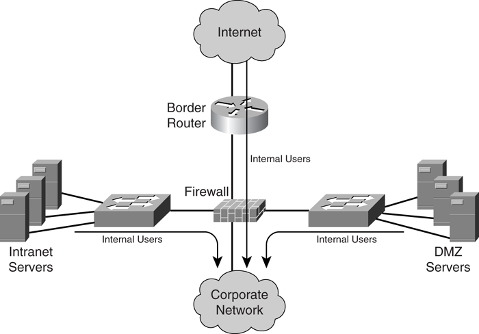
Routing for the internal users relies solely on the Interior Gateway Protocol (IGP) (for example, Open Shortest Path First [OSPF] or Enhanced Interior Gateway Routing Protocol [EIGRP]). In this case, both the address blocks of the intranet and DMZ server subnets are advertised by the IGP and made known to the rest of the network. For access to the Internet, a default route is injected into the network by the border router. In this manner, all traffic destined for the Internet is steered toward the border router.
One thing to take note of with Internet access is the method of routing required between the border router and the service provider. This method depends on the arrangement with the service provider in areas such as addressing, routing, and the redundancy strategy. One method is done via default routing, in which the border router just points a default route to the service provider’s network. The other method is to have the border router run a dynamic protocol with the service provider.
The choice between default and dynamic routing depends on the redundancy strategy for the Internet module. When only a single link is providing the Internet access, pointing the default route to the service provider is always recommended, because it is simple to implement. However, the network design can get a little complicated, even with the internal routing, when a resilient design is involved. For example, you may choose to have multiple border routers to provide multiple exit points to the Internet. When there are multiple exit points to the Internet within the network, how do you then decide which border router to use? You may choose to route traffic by the proximity of the source to the border routers, but you may have to consider the cost of sending the traffic to a particular border router, the service level agreement that you may have with a particular service provider, or even performance implications when selecting a particular exit point. Also, you must take care to prevent suboptimal routing and traffic black holes in such a scenario.
The complication with multiple exit points for the Internet is discussed in further detail in the section “[Establishing Internet Module Redundancy](https://learning.oreilly.com/library/view/building-resilient-ip/1587052156/ch07.html#ch07sec1lev2).”
##### Routing for External Users
As illustrated in [Figure 7-2](https://learning.oreilly.com/library/view/building-resilient-ip/1587052156/ch07.html#ch07fig02), routing for external users involves providing reachability to the DMZ subnet.
**Figure 7-2** _Routing for External Users_
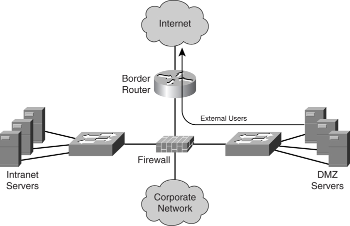
A common strategy is to assign the DMZ servers a public address block. It may be possible for the DMZ servers to be assigned a private address block. However, this involves a more complex implementation with the involvement of NAT, which is covered in the section “[Network Address Translation](https://learning.oreilly.com/library/view/building-resilient-ip/1587052156/ch07.html#ch07sec1lev5).”
It is important to point out that providing reachability to the DMZ subnet for the external users is governed by the routing arrangement with the service provider. In the event of a corporate network receiving the public address block via the lending scheme and default routing being adopted, the service provider already knows how to reach the DMZ subnet. There is no need to advertise the DMZ address block to the service provider. However, the routing arrangement with the service provider can get really complicated, depending on the addressing scheme and the redundancy strategy being adopted. This is especially so for networks that require multiple connections to the Internet. Depending on the factors such as routing policy, cost of access, or load-balancing requirements, the network design typically involves running dynamic routing with the service providers, as discussed in detail in the next section.
### Establishing Internet Module Redundancy
The availability of the Internet module is critical to an organization because business is conducted through the Internet. One important consideration when designing the Internet module is its redundancy strategy. You can achieve a redundant design for the Internet module in various ways, as follows:
• Link-level redundancy
• Device-level redundancy
• ISP-level redundancy
• Site-level redundancy
Each method provides protection against failure at a certain level of the network connectivity. When it comes to the differences between these methods, cost is often a major consideration because it is the single most expansive recurring cost when it comes to Internet connectivity.
#### Link-Level Redundancy
With Internet connections, the link between the corporate network and the service provider has traditionally been recognized as the weakest link. This is probably due to historical reasons when the WAN was considered unreliable as compared to the internal network links.
[Figure 7-3](https://learning.oreilly.com/library/view/building-resilient-ip/1587052156/ch07.html#ch07fig03) shows a border router with dual links connected to the service provider. You can achieve link-level redundancy in various ways, depending on the services made available from the service provider. One way is via link-bundling features, such as Multilink PPP (MLP). In MLP, multiple interfaces are bundled together and viewed as a single logical interface. This method achieves link redundancy and improves performance because multiple links are transmitting at the same time.
**Figure 7-3** _Link-Level Redundancy_
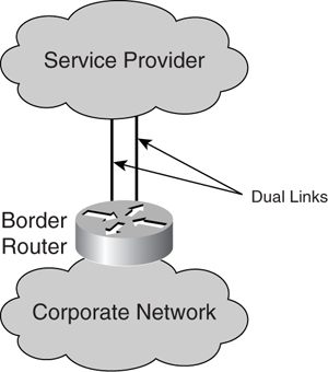
Another way to achieve link redundancy is via on-demand dial backup. In this scenario, an on-demand link is used for backup purposes. The on-demand link can be a simple dial-up line or ISDN. When the primary link fails, the border router brings up the on-demand interface for an alternate connection. With the availability of higher-speed Internet connectivity, the on-demand dial backup solution is becoming less popular because the technology lacks speed. It may not be as helpful to back up a high-speed link, such as a 100-Mbps Ethernet, with a 128-Kbps ISDN link.
For connection to the service provider via a Packet over SONET (POS) interface, link redundancy can be achieved through the implementation of the Automatic Protection Switching (APS) feature. APS allows for a secondary POS connection to be a backup of the primary connection. In the event of a primary POS connection failure, the secondary takes over immediately.
Link-level redundancy protects the Internet module from a link-related failure. It is usually a straightforward solution, but the link-redundancy scenarios can get complicated as more devices are involved, as illustrated in the next section.
#### Device-Level Redundancy
Device-level redundancy takes the link-level redundancy strategy a step further. When links are protected, the next single point of failure is the border router itself. To remain connected when the border router fails, a secondary border router needs to be in place, as illustrated in [Figure 7-4](https://learning.oreilly.com/library/view/building-resilient-ip/1587052156/ch07.html#ch07fig04).
**Figure 7-4** _Device-Level Redundancy_
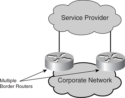
The complication with device-level redundancy lies in the routing design. Default routing is used when there is no routing protocol running between the corporate network and the service provider. The configuration at each of the border routers is straightforward in this case: They both point default routes to the service provider’s router. However, it is the propagation of the routing information within the corporate network that is tricky. Because there will be two routers announcing a default route, you have to decide which takes precedence. This requires you to make a decision on how traffic is to leave the corporate network or how the traffic load is going to be split between the two links. In either implementation, you need to implement some form of a floating static route.
Another routing design is to run a dynamic routing protocol between the border routers and the service providers. This design can get really complex because of the various possible combinations of setup. The dynamic routing protocol used in this case will almost always be BGP. Implementation of BGP requires you to have knowledge of concepts such as autonomous system (AS) number and route control via policy propagation. More details on BGP can be found in the section “[Border Gateway Protocol](https://learning.oreilly.com/library/view/building-resilient-ip/1587052156/ch07.html#ch07sec1lev4)” later in this chapter.
#### ISP-Level Redundancy
ISP-level redundancy, or _multihoming_, is next when you take device-level redundancy one step further. By subscribing Internet connectivity through different service providers, your Internet module is protected when there is a problem in one of the service provider’s networks. Another motivation is that it provides traffic load balancing across the multiple service providers. This is done at times when you are trying to improve application characteristics, such as performance and latency. Of course, multihoming design has cost implications and is mostly used by major corporate networks that cannot afford any failure in Internet connectivity.
The challenge with multihoming lies in its addressing and routing complexity, because the address blocks used will not solely belong to any service providers. Routing policy has to be carefully planned out, and you have to know the best practices to advertise routes in order to improve network resiliency. Another implication of multihoming is that service providers cannot aggregate this address block, which leads to an increased load on the overall routing of the Internet systems.
The two addressing options to consider with multihoming are as follows:
• The corporate network uses its own public address block. This is a straightforward implementation in which the address block is advertised to the upstream service providers.
• Use public address blocks assigned by the different service providers. This option is not as common because of the complexity of addressing and routing decisions. For example, you must determine how to allocate the various blocks of public addresses to the servers. In addition, because the addresses were obtained via the lending scheme, when there is a change in the service providers, the part of the server farm that had been using the old public address must be changed to the address provided by the new service provider. Solutions to such a scenario exist, one of which may involve the use of NAT.
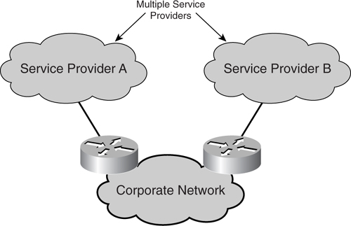
[Figure 7-5](https://learning.oreilly.com/library/view/building-resilient-ip/1587052156/ch07.html#ch07fig05) shows a corporate network “multihomed” to two different service providers. A good place to start to appreciate what is involved in the addressing and routing of a multihomed scenario is RFC 2260, _Scalable Support for Multi-homed Multi-provider Connectivity_. The RFC discusses the implication of increasing multihomed corporate networks on the routing system within the Internet. RFC 2260 also describes various routing and addressing strategies to cater to multihomed networks. As such, it is critical that you have a good understanding of this RFC and its implication on your network.
**Figure 7-5** _ISP-Level Redundancy_
#### Site-Level Redundancy
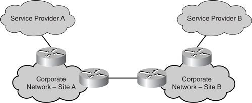
Besides connecting to multiple service providers to increase the availability of the Internet module, another strategy is to have multiple border routers residing in multiple sites. This way, when disaster strikes at one location, the network is still reachable via another exit point provided by a remote site or, in some cases, multiple sites. As illustrated in [Figure 7-6](https://learning.oreilly.com/library/view/building-resilient-ip/1587052156/ch07.html#ch07fig06), a corporate network has two sites, site A and site B, connected via its internal WAN link. The different border routers in those sites connect to different service providers.
**Figure 7-6** _Site-Level Redundancy_
A multisite Internet module is the most costly of all resiliency strategies because real estate cost is involved. In some extremely large corporate networks, it is common to have more than one site residing in different countries. The Cisco Systems internal network is one good example.
Whichever resiliency strategy you adopt, it is always recommended that you are familiar with the BGP routing protocol and the NAT feature. Both of these are critical tools for the Internet module, and they are described in greater detail in the sections “[Border Gateway Protocols](https://learning.oreilly.com/library/view/building-resilient-ip/1587052156/ch07.html#ch07sec1lev4)” and “[Network Address Translation](https://learning.oreilly.com/library/view/building-resilient-ip/1587052156/ch07.html#ch07sec1lev5).”
### Implementing Security Measures
With the proliferation of worms, viruses, and DoS attacks, it is not surprising that security is one critical consideration for the Internet module. Many network managers associate security at the Internet module with the placement of a firewall. However, you need more than just a box to protect the network from malicious attacks.
Because attacks such as worms and DoS can cripple a network, their effect is the same as that of a hardware failure or link failure to the Internet. Hence, you can no longer discuss resiliency to the Internet module without talking about security.
Security is a wide topic and warrants extensive research by itself. This section covers security policy and how it affects the design of the Internet module.
#### Security Policy
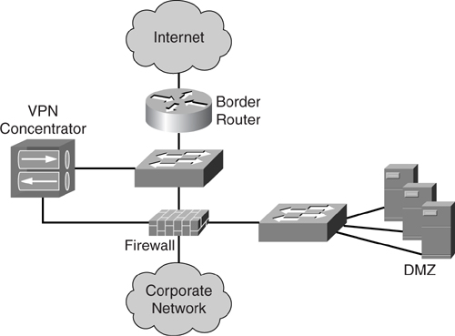
Many network managers recognize [Figure 7-7](https://learning.oreilly.com/library/view/building-resilient-ip/1587052156/ch07.html#ch07fig07) as the basic design of an Internet module: a firewall, border router, and a network carved out into an outside (Internet), inside (corporate network), and DMZ network.
**Figure 7-7** _Basic Internet Module Design_
Note
This section, “[Security Policy](https://learning.oreilly.com/library/view/building-resilient-ip/1587052156/ch07.html#ch07sec2lev7),” is based on a Cisco Systems presentation titled _Internet-edge Routing Concerns_ by James Christopher.
The design in [Figure 7-7](https://learning.oreilly.com/library/view/building-resilient-ip/1587052156/ch07.html#ch07fig07) may seem straightforward. However, the intricacy of the Internet module lies in the definition of the security policy rather than the actual physical connectivity.
Unlike the rest of the network modules, the starting point of the Internet module design is the security policy. As outlined by Cisco, the following are the five basic principles of a security policy:
• **Identity**—Identifies the hosts and applications that are affected by the policy. Address spoofing, or an attack based on a forged IP address, is a major identity concern in the Internet. As such, this portion of the security policy deals with the problem by taking action based on Layer 3 and Layer 4 information embedded within the IP packet.
• **Trust**—Determines under what condition hosts can communicate with each other. Whereas the traditional way of enforcing trust is via Layer 3 information, sophistication of technology enables you to enforce this even at Layer 2. One good example of the implementation of the private VLAN feature.
• **Enforcement**—Establishes how you implement the policy. The task of enforcement is further broken down to subtasks of secure, monitor, audit, and manage. Securing the infrastructure involves implementation of identity and authentication, encryption, and filtering and stateful inspection of traffic. Monitor deals with intrusion detection and traffic pattern monitoring. Audit is the process where security posture of the network is accessed and vulnerability of the network identified. Manage deals with the actual implementation of the devices, as well as event and data analysis on a day-to-day basis. Collectively, these subtasks help in enforcing the security policy for the network.
• **Risk assessment**—Determines the impact if the policy is breached. Hackers are constantly improving their ways of attack. Although the security policy is being enforced and the network is safe thus far, you will never be sure that it is going to be safe in the future. One important step is to study the impact of a breach. If the consequence proves too much for the corporation, perhaps connection to the Internet needs to be reassessed.
• **Incident response**—Establishes what actions to take when the policy is breached. Network managers should ask themselves whether they know exactly what to do when there is a security breach. In fact, there should be different actions drawn up with respect to different security breaches. Security breaches come in different levels of severity. There are basically five levels of breach:
—**Known vulnerability**—A defect may be discovered because of a security audit or a vendor’s announcements about code defects. This is the least severe because you have time to reconfigure or to apply patches.
—**Reconnaissance**—The network is being scanned and probed and this is when you realize that there may be an impending attack on your network, or at least there is some interest in gaining unlawful access to the network.
—**Misuse**—This is when unauthorized or inappropriate network activity is discovered.
—**Attack**—This is when the actual action of compromising the network resources is taking place.
—**Compromised**—This is when the attack was successful and the resulting network may or may not be functioning, depending on the severity of the attack.
Basic security policies for the network should encompass these five principles. An essential part of the configuration of the Internet module encompasses these principles and is done through a series of filtering, as shown in the next section.
#### Filtering at the Internet Module
Part of the security requirement for the Internet module is achieved through the implementation of a series of filters planted at the border routers. These filters, known as transit access control lists (ACLs), are an important first line of defense against malicious activities.
The border routers of the Internet module provide the first line of defense through the deployment of inbound ACLs. These ACLs allow only permitted traffic to the DMZ server farm and for internal users to exit to the Internet. All unauthorized traffic should be dropped on the interface facing the Internet.
In general, the inbound ACLs should perform the following tasks:
• Basic filtering for private, special-use address and antispoofing measures. This task denies address space as stipulated in RFC 1918. It also prevents traffic with source addresses that belong to the special-use address space as defined in RFC 3330, _Special-Use IPv4 Addresses_. In addition, this task prevents traffic with source addresses belonging to the internal network from entering via the Internet-facing interface. You can find the antispoofing guidelines in RFC 2827, _Network Ingress Filtering: Defeating Denial of Service Attacks Which Employ IP Source Address Spoofing_.
• Explicitly permit return traffic for internal connections to the Internet. This traffic may include the following:
—Specific Internet Control Message Protocol (ICMP) types
—Outbound Domain Name System (DNS) query replies
—Established TCP traffic
—User Datagram Protocol (UDP) return traffic
—File Transfer Protocol (FTP) data connections
• Explicitly permit external traffic destined to the DMZ or a predefined address block. These may include the following:
—HTTP traffic
—Virtual Private Network (VPN) traffic
—Simple Mail Transfer Protocol (SMTP)
—Inbound FTP data connections
—Inbound DNS traffic
• Explicitly deny other traffic.
[Example 7-1](https://learning.oreilly.com/library/view/building-resilient-ip/1587052156/ch07.html#ch07ex01) shows a sample configuration. It is important to further develop the following to suit your network environment before implementing it.
**Example 7-1** _Sample Filtering at the Internet Module_
---
Router#configure terminal
!Add anti-spoofing entries.
!Deny special-use address sources.
!Refer to RFC 3330 for additional special use addresses.
Router(config)#access-list 110 deny ip 127.0.0.0 0.255.255.255 any
Router(config)#access-list 110 deny ip 192.0.2.0 0.0.0.255 any
Router(config)#access-list 110 deny ip 224.0.0.0 31.255.255.255 any
Router(config)#access-list 110 deny ip host 255.255.255.255 any
!The deny statement below should not be configured
!on Dynamic Host Configuration Protocol (DHCP) relays.
Router(config)#access-list 110 deny ip host 0.0.0.0 any
!Filter RFC 1918 space.
Router(config)#access-list 110 deny ip 10.0.0.0 0.255.255.255 any
Router(config)#access-list 110 deny ip 172.16.0.0 0.15.255.255 any
Router(config)#access-list 110 deny ip 192.168.0.0 0.0.255.255 any
!Permit Border Gateway Protocol (BGP) to the edge router.
Router(config)#access-list 110 permit tcp host bgp_peer IP gt 1023 host edge
router_ip eq bgp
Router(config)#access-list 110 permit tcp host bgp_peer IP eq bgp host edge
router_ip gt 1023
!Deny your space as source (as noted in RFC 2827).
Router(config)#access-list 110 deny ip your Internet-routable subnet any
!Explicitly permit return traffic. Allow specific ICMP types.
Router(config)#access-list 110 permit icmp any any echo-reply
Router(config)#access-list 110 permit icmp any any unreachable
Router(config)#access-list 110 permit icmp any any time-exceeded
Router(config)#access-list 110 deny icmp any any
!Outgoing DNS queries are shown below.
Router(config)#access-list 110 permit udp any eq 53 host primary DNS server IP gt
1023
!Permit older DNS queries and replies to primary DNS server.
Router(config)#access-list 110 permit udp any eq 53 host primary DNS server IP eq 53
!Permit legitimate business traffic.
Router(config)#access-list 110 permit tcp any Internet-routable subnet established
Router(config)#access-list 110 permit udp any range 1 1023 Internet-routable subnet
gt 1023
!Internet-sourced connections to publicly accessible servers are shown below
Router(config)#access-list 110 permit tcp any host public web server IP eq 80
Router(config)#access-list 110 permit tcp any host public web server IP eq 443
Router(config)#access-list 110 permit tcp any host public FTP server IP eq 21
!Data connections to the FTP server are allowed
!by the permit established ACE.
!Allow PASV data connections to the FTP server.
Router(config)#access-list 110 permit tcp any gt 1023 host public FTP server IP gt
1023
Router(config)#access-list 110 permit tcp any host public SMTP server IP eq 25
!Explicitly deny all other traffic.
Router(config)#access-list 101 deny ip any any
---
Although the guidelines seem simple to follow, the difficult part in developing transit ACL is in determining what traffic or protocol is allowed and what is not allowed for your network. It is important that you find out what is applicable within your network, because not all networks are the same. Some basic protocols are common to most networks, however. For example, if you have a web server in the DMZ that provides information for external users, you need to permit TCP traffic to the DMZ via port 80. The task of developing the transit ACL is extremely important, because any mistake you make here can have drastic consequences, such as denying legitimate traffic or, in the worst case, exposing some servers or applications to hacking.
As part of the implementation of the transit ACL, here are some good points to remember:
• Never allow a direct connection to be initiated by an external host to an internal host. At no time can this rule be bent.
• In the event that you allow external hosts to initiate a connection to a host within your network, place the internal host in the DMZ.
• Be extremely careful with ICMP and UDP traffic flowing both in and out of the Internet module. Although DNS traffic, such as zone updates, may be allowed, you have to be strict with other ICMP or UDP traffic.
• Avoid an application design that makes use of tunneling or port redirection (for example, remote desktop or file system redirection).
• An antispoofing mechanism has to be applied on the Internet connection; RFC 2827 is a mandatory literature. The intent of anti-spoofing is to make sure that traffic from the Internet is not trying to spoof an internal address.
• All management traffic must be encrypted. For this, the Cisco IOS code with Secure Shell (SSH) is recommended. (SSH is a more secure alternative to Telnet.) For a device that is manageable via the web, SSL has to be implemented. For authentication and logging purposes, facilities such as Terminal Access Controller Access Control System (TACACS) have to be in place.
• NAT can be used to protect internal hosts from being directly connected via an external host.
• Traffic from the Internet should neither be sourced nor destined to a private IP address. Therefore, private IP filtering has to be in place at the border router.
• To provide remote access via the Internet, the VPN termination can be done on the firewall or parallel to the firewall, if there is a separate device. In other words, remote-access traffic needs to be scrutinized by the firewall.
• Stateful inspection has to be implemented so that packets that fail to match a proper TCP state are dropped.
• Rate limiting of traffic may be implemented based on a set threshold. Rate limiting proves useful to control traffic so as to prevent excessive bandwidth consumption.
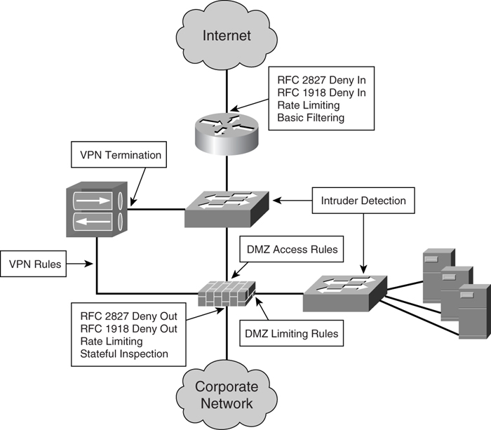
[Figure 7-8](https://learning.oreilly.com/library/view/building-resilient-ip/1587052156/ch07.html#ch07fig08) shows the significance of the various security measures in the Internet module. Because security is a big topic by itself, you are advised to refer to documentation that offers a more in-depth discussion. A good point of reference is the Cisco SAFE Blueprint
at the following URL:
[http://www.cisco.com/en/US/netsol/ns340/ns394/ns171/ns128/networking_solutions_package.html](http://www.cisco.com/en/US/netsol/ns340/ns394/ns171/ns128/networking_solutions_package.html)
**Figure 7-8** _Various Security Measures in the Internet Module_
### Resilient Border Gateway Protocol (BGP) Design
The BGP is an interdomain routing protocol used to exchange routing information between autonomous systems. It is the _de facto_ standard for routing within the Internet.
With more and more corporate networks getting connected to the Internet, BGP is becoming an integral part of the Internet module within a corporate network’s IP infrastructure. With the growing importance of ensuring continuous operation for the Internet, much research and development efforts have been spent on improving the protocol in the area of resiliency and process optimization.
Because BGP is responsible for the Internet connection for a network, its operational status is critical to the overall health of the network. One common comment about BGP as a protocol is its slowness in response to network events, and as such, its slow convergence. This is in part due to its scanner process, which is scheduled once every 60 seconds. Since its inception, BGP has not only undergone updates and expansion in features, but much work has been done on improving its response to network events and its convergence. For a good refresher on BGP, you may want to refer to _Internet Routing Architectures_, Second Edition, by Sam Halabi (Cisco Press, 2000).
The following sections illustrate some of the improvements to BGP, including soft reconfiguration, convergence optimization, next-hop address tracking, fast peering session deactivation, and IP event dampening.
#### BGP Soft Reconfiguration
In BGP, the exchange of routes between two autonomous systems is maintained by the eBGP peering session between the border routers. The border routers’ behaviors are governed by the routing policies, which include configurations such as route map, filter list, and distribute list. Whenever there is a change in the routing policies on either side, the BGP session has to be cleared for the new policy to take effect. There are two ways to clear the BGP sessions:
• Hard reset
• Soft reset
When the BGP session is cleared with the hard reset option, the route cache of the router is flushed, causing a loss of routing information. When this happens, the router, or the network, is no longer able to forward traffic to its neighbor network. In soft reset, the routing table is not flushed and, therefore, the impact on the router is minimal. Soft reset is preferred over the hard reset because its impact on the overall network is minimal.
Soft reset can be used for both inbound and outbound updates. When it is used to generate inbound updates from a neighbor, it is called an _inbound soft reset_. There are two ways to perform an inbound soft reset:
• **Using stored routing update information**—In this method, in order not to reset the BGP session, the router needs to store all received updates from its neighbor without modifications. This requires a lot of memory resources and is an operation that is detrimental to the well-being of the router. This is also known as the soft-reconfiguration inbound feature.
• **Using dynamic soft reset**—This method is an improvement over the first, because it provides for automatic support for dynamic soft reset that does not depend on the stored routing updates. This is done through the enhancement to the BGP code within the IOS. Therefore, it requires less memory and is the preferred method. This enhancement over the first is also called the _route refresh_ capability. The first method needs preconfiguration, whereas the enhanced method does not need configuration.
When the soft reset feature is used to send a new set of updates to a neighbor, it is called an _outbound soft reset_. There is only one way to perform outbound soft reset: dynamic soft reset.
With the enhanced method, no preconfiguration is required. However, you need to verify that the peer supports the route refresh capability via the **show ip bgp neighbors** command. In [Figure 7-9](https://learning.oreilly.com/library/view/building-resilient-ip/1587052156/ch07.html#ch07fig09), router R15 has an external peer, R16, that supports the soft reset capability.
**Figure 7-9** _BGP Peer with Route Refresh Capability_
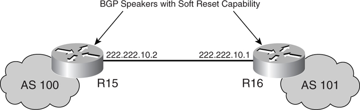
When its external peer supports this capability, the message highlighted in [Example 7-2](https://learning.oreilly.com/library/view/building-resilient-ip/1587052156/ch07.html#ch07ex02) displays on R15.
**Example 7-2** _Status of BGP Peer with Route Refresh Capability_
---
R15#show ip bgp neighbors 222.222.10.1
BGP neighbor is 222.222.10.1, remote AS 101, external link
BGP version 4, remote router ID 222.222.10.1
BGP state = Established, up for 00:00:24
Last read 00:00:24, hold time is 180, keepalive interval is 60 seconds
Neighbor capabilities:
Route refresh: advertised and received(old & new)
Address family BGP IPv4: advertised and received
---
With the route refresh capability, you can then issue the following command on R15 to reset the inbound routing table:
R15#clear ip bgp 222.222.10.1 in
For outbound soft reset, you can issue the following command:
R15#clear ip bgp 222.222.10.1 out
On the other hand, R14 peers with R13, which does not have the soft reset capability. The status message on R14 looks different from R15’s when its peer does not support the soft reset feature, as shown in [Example 7-3](https://learning.oreilly.com/library/view/building-resilient-ip/1587052156/ch07.html#ch07ex03).
**Example 7-3** _Status of BGP Peer Without Soft Reset Capability_
---
R14#show ip bgp neighbors 222.222.10.6
BGP neighbor is 222.222.10.6, remote AS 103, external link
BGP version 4, remote router ID 222.222.10.6
BGP state = Established, up for 00:00:22
Last read 00:00:22, hold time is 180, keepalive interval is 60 seconds
Neighbor capabilities:
Route refresh: advertised
Address family IPv4 Unicast: advertised and received
---
In this case, the preconfiguration method (soft-reconfiguration inbound) may be considered. However, the performance impact on the router has to be examined carefully. [Example 7-4](https://learning.oreilly.com/library/view/building-resilient-ip/1587052156/ch07.html#ch07ex04) shows the preconfiguration method of inbound soft reset.
**Example 7-4** _Inbound Soft Reset with Preconfiguration_
---
Router A
interface serial 1/0
ip address 222.222.10.5 255.255.255.252
router bgp 100
neighbor 222.222.10.6 remote-as 103
neighbor 222.222.10.6 soft-reconfiguration inbound
---
With the preconfigured inbound soft reset, the status of the peer is reflected in [Example 7-5](https://learning.oreilly.com/library/view/building-resilient-ip/1587052156/ch07.html#ch07ex05).
**Example 7-5** _BGP Status with Soft Reset Preconfiguration_
---
R14#show ip bgp neighbors 5.5.5.11
BGP neighbor is 5.5.5.11, remote AS 103, external link
BGP version 4, remote router ID 5.5.5.11
BGP state = Established, up for 00:00:13
Last read 00:00:13, hold time is 180, keepalive interval is 60 seconds
Neighbor capabilities:
Route refresh: advertised
Address family IPv4 Unicast: advertised and received
IPv4 MPLS Label capability:
Received 133 messages, 0 notifications, 0 in queue
Sent 139 messages, 0 notifications, 0 in queue
Default minimum time between advertisement runs is 30 seconds
For address family: IPv4 Unicast
BGP table version 1, neighbor version 1
Index 3, Offset 0, Mask 0x8
Inbound soft reconfiguration allowed
Route refresh request: received 0, sent 0
0 accepted prefixes consume 0 bytes
Prefix advertised 0, suppressed 0, withdrawn 0
---
The BGP soft reconfiguration feature allows for policies to be changed without affecting the BGP session. When you maintain the BGP session, the routing of the network is kept in steady state and, thus, operation of the network is not impacted.
#### BGP Convergence Optimization
BGP convergence optimization refers to a series of IOS code enhancements and configuration recommendations to improve BGP’s convergence performance. Basically, the IOS developers look at the various factors that are involved in the BGP operation and look for ways to improve these individual factors to contribute to the overall performance. These factors include the following:
• TCP frame optimization
• Input queues
• Maximum transmission unit (MTU) size
• Update packing
• Peer group
A BGP speaker relies on a TCP session for its interaction with its peer. Before the enhancement, the BGP process did not fully make use of the available TCP frame size for its transmission. This results in slow update propagation. Enhancement was made to the IOS code to improve on this.
From experience, a BGP speaker experiences a large number of dropped TCP acknowledgments when sending updates to multiple peers. This degrades the BGP performance and affects convergence. This is in part due to the default input queue size of the interface being swamped by the TCP acknowledgments. By changing the queue size to 4096 via the **hold-queue** command, you can greatly reduce the number of dropped TCP acknowledgments and will see a marked improvement in performance.
The default TCP maximum segment size (MSS) is 536 bytes on a router. This setting may not be efficient for today’s network, especially with high-speed interfaces such as Gigabit Ethernet. The efficiency of the BGP process can be improved if the MSS is optimized with respect to the interface used. You can do this via the **ip tcp path-mtu-discovery** command.
A BGP update consists of a list of network layer reachability information (NLRI) that shares the same attributes. The more NLRI sent within an update, the more efficient the BGP process will be. This is what update packing tries to achieve. The improvement to convergence varies with update packing, because this depends on the attributes and the table size.
When a BGP speaker needs to send updates to its peer, it needs to go through its table once and subject the prefixes to the outbound policies. This has to be done once on a per-peer basis. When multiple peers are involved, especially with a large prefix table, this process becomes a control-plane-intensive exercise and convergence takes a long time. The solution to this is to make use of the peer group feature. With the peer group feature, the update generation needs to be done only once and sent to a peer group leader. The update is then replicated by the leader to peer members. Update generation still requires walking through the prefix table and outbound policies, but update replication does not have to be and is more efficient. The improvement to convergence can be significant, especially with a large peer group.
You can achieve a vast improvement to the BGP convergence via the combination of the above enhancements and configuration recommendations. With a more efficient BGP process and improved convergence, the resiliency of the Internet module can be greatly improved.
#### BGP Next-Hop Address Tracking
The BGP next-hop address tracking feature obsoletes the BGP scanner process, and allows BGP to respond quickly to changes to the next hop so as to improve its convergence time.
As mentioned, the BGP scanner is a process that monitors the next-hop state so as to ascertain the validity of the installed routes. By default, this process does its job every 60 seconds. Therefore, any network failure that relates to the next hop will not be handled by BGP until the next scanning cycle. With the next-hop address tracking feature, any changes to the next-hop status is quickly reported to the BGP protocol. This bypasses the 60-second requirement and improves BGP’s capability to respond to network events. This also removes the control-plane load introduced by the scanner process and, therefore, improves the overall performance and stability of the router.
This feature is available in Cisco IOS Releases 12.0(29)S and 12.3(14)T and later, and is enabled by default. However, you may choose to turn it off with the commands shown in [Example 7-6](https://learning.oreilly.com/library/view/building-resilient-ip/1587052156/ch07.html#ch07ex06).
**Example 7-6** _Disabling BGP Next-Hop Address Tracking_
---
router#config terminal
router(config)#router bgp 100
router(config-router)#address-family ipv4 unicast
router(config-router-af)#no bgp nexthop trigger enable
---
#### BGP Support for Fast Peering Session Deactivation
The BGP support for the fast peering session deactivation feature is part of the overall BGP convergence improvement effort. This event-driven feature allows BGP to monitor its peering sessions with its neighbors. Upon detection of a loss of session due to whatever reason, this feature allows BGP to terminate the session immediately, bypassing the scanner cycle and the BGP hold timer, which is 3 minutes by default. This way, BGP can clean up routes in a much faster manner, and thus improve its convergence time.
This feature is available in Cisco IOS Releases 12.0(29)S and 12.3(14)T and later. [Example 7-7](https://learning.oreilly.com/library/view/building-resilient-ip/1587052156/ch07.html#ch07ex07) shows a sample configuration.
**Example 7-7** _Enabling BGP Fast Peering Session Deactivation_
---
router#config terminal
router(config)#router bgp 100
router(config-router)#address-family ipv4 unicast
router(config-router-af)#neighbor 10.1.1.1 remote-as 101
router(config-router-af)#neighbor 10.1.1.1 fall-over
---
#### BGP Route Dampening
An observation that you can make with a router running BGP is that it goes through a series of steps to make sure all routes that it learned are in place before introducing these routes into its forwarding table, and before advertising the routes to its BGP peers. Therefore, when an external route is toggling between available and unavailable in rapid successions (better known as route flap), not only does the router need to process this change of states, but it also needs to send out the withdrawal and update messages to its peers. Route flap is bad because it causes load on the control plane of the routers running BGP, and, in the worst case, it actually has the same effect as a DoS attack on itself.
BGP route dampening is a feature that reduces the effect of route flap in the functioning of the BGP process. It introduces an exponential decay mechanism, which is configurable, so that this effect can be minimized. If the route is dampened, the BGP will not take its status into consideration until it has stopped flapping. With the route-dampening feature, the control plane of the router is protected, unnecessary network convergence can be prevented, and network stability is greatly enhanced.
[Example 7-8](https://learning.oreilly.com/library/view/building-resilient-ip/1587052156/ch07.html#ch07ex08) shows the command used to configure BGP route dampening with default values.
**Example 7-8** _Configuring BGP Route Dampening_
---
R2#configure terminal
R2(config)#router bgp 100
R2(config-router)#bgp dampening
---
[Example 7-9](https://learning.oreilly.com/library/view/building-resilient-ip/1587052156/ch07.html#ch07ex09) shows the BGP dampening status of a router.
**Example 7-9** _Displaying BGP Dampening Status_
---
R2#show ip bgp dampening parameters
dampening 15 750 2000 60 (DEFAULT)
Half-life time : 15 mins Decay Time : 2320 secs
Max suppress penalty: 12000 Max suppress time: 60 mins
Suppress penalty : 2000 Reuse penalty : 750
R2#
---
#### Nonstop Forwarding with Stateful Switchover (NSF/SSO) for BGP
The Nonstop Forwarding with Stateful Switchover (NSF/SSO) feature allows a router with dual route processors to maximize its overall availability. With NSO/SSO, when the primary route processor fails, the standby route processor can take over the operation of the router with minimal traffic disruption. As illustrated in [Chapter 3](https://learning.oreilly.com/library/view/building-resilient-ip/1587052156/ch03.html#ch03), “[Fundamentals of IP Resilient Networks](https://learning.oreilly.com/library/view/building-resilient-ip/1587052156/ch03.html#ch03),” unlike Route Processor Redundancy Plus (RPR+), NSF/SSO allows the router to maintain the data link layer connections and continue forwarding packets during the switchover to the secondary processor. The forwarding operation continues to take place even though there is a loss in routing protocol peerings. As the router recovers, routing protocols continue to be restored dynamically in the background until everything is back to normal.
In normal BGP operation, when there is a switchover of route processors in a local router, the TCP connection between the local router and its remote peer is taken down. Therefore, the remote peer starts to clear all routes that are associated with this local router and stops forwarding traffic to it. With the NSF/SSO for BGP feature, this does not happen. It essentially allows the remote router to continue its forwarding operation to the local router when such a catastrophic event occurs. This is essentially the combination of the NSF/SSO feature and enhancements that have been made to the BGP protocol.
Suppose that you intend to turn on the NSF/SSO for BGP in your local router, which has been installed with dual route processors. For NSF/SSO for BGP to work in the local router, several conditions must be met:
• The local and remote router must agree to support the BGP graceful restart feature.
• The remote router must not prematurely declare the local router as unavailable when switchover occurs.
• The remote router must not communicate the state change (the switchover) to other peers. This is to avoid a network convergence from taking place.
• The remote router must send BGP updates to help the local router restore its BGP table.
• The remote router must have a way to tell the local router that it has finished sending the updates.
• While all this is taking place, the remote router must mark all routes associated with the local router as “stale.” However, it must continue to forward traffic destined for the local router.
The NSF/SSO for BGP feature requires the participation of remote devices for it to work. However, not every device has a dual processor configuration. Therefore, new concepts have been introduced: NSF capable and NSF aware. An NSF-capable device has dual processors and is running the same feature. On the other hand, a NSF-aware device has only a single processor but is capable of participating in the protocol. Therefore, whenever a device is neither NSF capable nor NSF aware, normal BGP routing behavior takes place. That means there will be traffic disruption when there is a processor switchover, because the TCP connections for the two peers are taken down.
Because the operation of the NSF/SSO for BGP involves maintaining states across the two route processors within the same router, it requires compatible hardware to be installed. As such, care must be taken before enabling this feature. The following are implementation guidelines:
• **Cisco 12000 series router**—Route processors must be of the same type. That is, a GRP route processor may be used only with another GRP route processor. And a PRP route processor may be used only with another PRP.
• **Cisco 10000 series router**—Route processors must be of the same type. That is, a PRE-1 route processor may be used only with another PRE-1 route processor. And PRE-2 may be used only with another PRE-2.
• **Cisco 7500 series router**—RSP-2 and RSP-4 may be used together, and RSP-8 and RSP-16 may be used together. However, these two groups of processors cannot be used together.
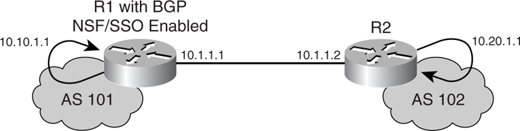
[Figure 7-10](https://learning.oreilly.com/library/view/building-resilient-ip/1587052156/ch07.html#ch07fig10) illustrates a sample setup for NSF/SSO for BGP between two routers, R1 and R2. R1 is configured with two route processors running in SSO mode.
**Figure 7-10** _Setup for NSF/SSO for BGP_
The first step in configuring NSF/SSO for BGP is to ascertain the redundancy level of the router as a whole, as shown in [Example 7-10](https://learning.oreilly.com/library/view/building-resilient-ip/1587052156/ch07.html#ch07ex10).
**Example 7-10** _Determining the Redundancy Status of a Router_
---
R1#show redundancy
Redundant System Information :
------------------------------
Available system uptime = 4 days, 4 hours, 26 minutes, 11 seconds
Switchovers system experienced = 0
Standby failures = 1
Last switchover reason = none
Hardware Mode = Duplex
Configured Redundancy Mode = SSO
Operating Redundancy Mode = SSO
Maintenance Mode = Disabled
Communications = Up
Current Processor Information :
-------------------------------
Active Location = slot 4
Current Software state = ACTIVE
Uptime in current state = 4 days, 4 hours, 25 minutes, 55 seconds
Image Version = Cisco Internetwork Operating System Software
IOS (tm) GS Software (C12KPRP-P-M), Version 12.0(28)S1, RELEASE SOFTWARE (fc1)
Technical Support: http://www.cisco.com/techsupport
Copyright© 1986-2004 by cisco Systems, Inc.
Compiled Fri 27-Aug-04 21:13 by hqluong
BOOT = bootflash:c12kprp-p-mz.120-28.S1.bin,1;
CONFIG_FILE =
BOOTLDR =
Configuration register = 0x2102
Peer Processor Information :
----------------------------
Standby Location = slot 5
Current Software state = STANDBY HOT
Uptime in current state = 1 minute, 6 seconds
Image Version = Cisco Internetwork Operating System Software
IOS (tm) GS Software (C12KPRP-P-M), Version 12.0(28)S1, RELEASE SOFTWARE (fc1)
Technical Support: http://www.cisco.com/techsupport
Copyright© 1986-2004 by cisco Systems, Inc.
Compiled Fri 27-Aug-04 21:13 by hqluong
BOOT = bootflash:c12kprp-p-mz.120-28.S1.bin,1;
CONFIG_FILE =
BOOTLDR =
Configuration register = 0x2102
R1#
---
After the redundancy of the router R1 has been confirmed, the actual configuration of the protocol can begin. [Example 7-11](https://learning.oreilly.com/library/view/building-resilient-ip/1587052156/ch07.html#ch07ex11) shows a sample configuration for NSF/SSO for BGP on router R1.
**Example 7-11** _Configuring BGP with NSF/SSO on R1_
---
router bgp 101
no synchronization
bgp log-neighbor-changes
bgp graceful-restart restart-time 120
bgp graceful-restart stalepath-time 360
bgp graceful-restart
network 10.10.1.1 mask 255.255.255.255
neighbor 10.1.1.2 remote-as 102
no auto-summary
---
[Example 7-12](https://learning.oreilly.com/library/view/building-resilient-ip/1587052156/ch07.html#ch07ex12) shows a sample configuration for NSF/SSO for BGP on router R2.
**Example 7-12** _Configuring BGP with NSF/SSO on R2_
---
router bgp 102
no synchronization
bgp log-neighbor-changes
bgp graceful-restart restart-time 120
bgp graceful-restart stalepath-time 360
bgp graceful-restart
network 10.20.1.1 mask 255.255.255.255
neighbor 10.1.1.1 remote-as 101
no auto-summary
---
When the eBGP peering between the two routers has been established, the BGP status of R1 is as illustrated in [Example 7-13](https://learning.oreilly.com/library/view/building-resilient-ip/1587052156/ch07.html#ch07ex13).
**Example 7-13** _BGP Status of R1_
---
R1#show ip bgp neighbors 10.1.1.2
BGP neighbor is 10.1.1.2, remote AS 102, external link
BGP version 4, remote router ID 10.20.1.1
BGP state = Established, up for 00:20:36
Last read 00:00:36, hold time is 180, keepalive interval is 60 seconds
Neighbor capabilities:
Route refresh: advertised and received(new)
Address family IPv4 Unicast: advertised and received
Graceful Restart Capability: advertised and received
Remote Restart timer is 120 seconds
Address families preserved by peer:
IPv4 Unicast
---
Likewise, the BGP status of R2 is as illustrated in [Example 7-14](https://learning.oreilly.com/library/view/building-resilient-ip/1587052156/ch07.html#ch07ex14).
**Example 7-14** _BGP Status of R2_
---
R2#show ip bgp neighbors 10.1.1.1
BGP neighbor is 10.1.1.1, remote AS 101, external link
BGP version 4, remote router ID 10.10.1.1
BGP state = Established, up for 00:21:47
Last read 00:00:47, hold time is 180, keepalive interval is 60 seconds
Neighbor capabilities:
Route refresh: advertised and received(new)
Address family IPv4 Unicast: advertised and received
Graceful Restart Capability: advertised and received
Remote Restart timer is 120 seconds
Address families preserved by peer:
IPv4 Unicast
---
Because the two routers are running with no hardware issued at the beginning, a show of BGP route status and its forwarding table in R2 is as shown in [Example 7-15](https://learning.oreilly.com/library/view/building-resilient-ip/1587052156/ch07.html#ch07ex15).
**Example 7-15** _Route Status of R2_
---
R2#show ip bgp
BGP table version is 3, local router ID is 10.20.1.1
Status codes: s suppressed, d damped, h history, * valid, > best, i - internal,
r RIB-failure, S Stale
Origin codes: i - IGP, e - EGP, ? - incomplete
Network Next Hop Metric LocPrf Weight Path
*> 10.10.1.1/32 10.1.1.1 0 0 101 i
*> 10.20.1.1/32 0.0.0.0 0 32768 i
R2#show ip cef 10.10.1.1
10.10.1.1/32, version 15, epoch 0, cached adjacency 10.1.1.1
0 packets, 0 bytes
via 10.1.1.1, 0 dependencies, recursive
next hop 10.1.1.1, SRP0/0 via 10.1.1.1/32 (Default)
valid cached adjacency
---
Notice that the route to the loopback interface of R1, 10.10.1.1, is reflected in BGP as a valid and best path. In addition, the forwarding table in R2 shows valid information for the route and its next-hop interface. To show the effect of turning on NSF/SSO for BGP, initiate an extended ping session from the loopback interface of R2 to the loopback interface of R1. This is to ensure that both the forwarding tables of the routers have to be utilized for this experiment. Now, suppose the primary route processor in R1 encounters a problem during the experiment and is forced to switch over to the secondary route processor. [Example 7-16](https://learning.oreilly.com/library/view/building-resilient-ip/1587052156/ch07.html#ch07ex16) shows what happens in R2.
**Example 7-16** _Detecting Route Processor Switchover of Its Peer in R2_
---
R2#ping
Protocol [ip]:
Target IP address: 10.10.1.1
Repeat count [5]: 80000
Datagram size [100]:
Timeout in seconds [2]:
Extended commands [n]: y
Source address or interface: 10.20.1.1
Type of service [0]:
Set DF bit in IP header? [no]:
Validate reply data? [no]:
Data pattern [0xABCD]:
Loose, Strict, Record, Timestamp, Verbose[none]:
Sweep range of sizes [n]:
Type escape sequence to abort.
Sending 80000, 100-byte ICMP Echos to 10.10.1.1, timeout is 2 seconds:
!!!!!!!!!!!!!!!!!!!!!!!!!!!!!!!!!!!!!!!!!!!!!!!!!!!!!!!!!!!!!!!!!!!!!!
!!!!!!!!!!!!!!!!!!!!!!!!!!!!!!!!!!!!!!!!!!!!!!!!!!!!!!!!!!!!!!!!!!!!!!
!output omitted for brevity
4d05h: %BGP-5-ADJCHANGE: neighbor 10.1.1.1 Down NSF peer closed the
session!!!!!!!!!!!!!!!!!!!!!!!!!!!!!!!!!!!!!!!!!!!!!!!
!!!!!!!!!!!!!!!!!!!!!!!!!!!!!!!!!!!!!!!!!!!!!!!!!!!!!!!!!!!!!!!!!!!!!!
!!!!!!!!!!!!!!!!!!!!!!!!!!!!!!!!!!!!!!!!!!!!!!!!!!!!!!!!!!!!!!!!!!!!!!
!!!!!!!!!!!!!!!!!!!!!!!!!!!!!!!!!!!!!!!!!!!!!!!!!!!!!!!!!!!!!!!!!!!!!!
!!!!!!!!!!!!!!!!!!!!!!!!!!!!!!!!!!!!!!!!!!!!!!!!!!!!!!!!!!!!!!!!!!!!!!
!output omitted for brevity
4d05h: %BGP-5-ADJCHANGE: neighbor 10.1.1.1 Up !!!!!!!!!!!!!!!!!!!!!!
!!!!!!!!!!!!!!!!!!!!!!!!!!!!!!!!!!!!!!!!!!!!!!!!!!!!!!!!!!!!!!!!!!!!!!
!!!!!!!!!!!!!!!!!!!!!!!!!!!!!!!!!!!!!!!!!!!!!!!!!!!!!!!!!!!!!!!!!!!!!!
!!!!!!!!!!!!!!!!!!!!!!!!!!!!!!!!!!!!!!!!!!!!!
!!!!!!!!!!!!!!!!!!!!!!!!!!!!!!!!!!!!!!!!!!!!!!!!!!!!!!!!!!!!!!!!!!!!!!
!!!!!!!!!!!!!!!!!!!!!!!!!!!!!!!!!!!!!!!!!!!!!!!!!!!!!!!!!!!!
Success rate is 100 percent (80000/80000), round-trip min/avg/max = 1/1/4 ms
R2#
---
Notice that half way through the experiment, R2 detected that its neighbor has closed the BGP session, but it continues to forward the ping request. Likewise, R1 continues to reply to the ping request while its secondary route processor is taking over the control-plane function. Along the way, the BGP session is reestablished; the final result is seen at the bottom of the screen, which states a zero drop performance. In addition, notice that the latency is barely affected, with a range of 1 to 4 milliseconds.
As part of the NSF/SSO for BGP feature, after the BGP session is reestablished, BGP updates take place in the background so that R1 can rebuild its BGP table. This is reflected in the **debug** session of R2 shown in [Example 7-17](https://learning.oreilly.com/library/view/building-resilient-ip/1587052156/ch07.html#ch07ex17).
**Example 7-17** _BGP Updates on R2_
---
Router#
4d05h: %BGP-5-ADJCHANGE: neighbor 10.1.1.1 Up
4d05h: BGP(0): Begin update run for versions 1->4 for 1 update groups
4d05h: BGPNSF(0): send End-of-RIB for IPv4 Unicast to neighbor 10.1.1.1
4d05h: BGP(0): End update run for versions 1->4 (0ms), 1/1/0 updates formatted/e
nqueued/replicated, formatting was not aborted, enqueuing was not aborted, 1 att
rs - 1 nets visited
4d05h: BGPNSF(0): rcvd End-of-RIB for IPv4 Unicast from 10.1.1.1
4d05h: BGPNSF(0): Receiving router rcvd End-of-RIB from restarting peer 10.1.1.1
4d05h: BGP(0): Reset update-group 1 versions from 4 to (cand 10.1.1.1) 4
4d05h: BGPNSF: service NSF requests for AF IPv4 Unicast
4d05h: BGPNSF: NSF processing for IPv4 Unicast paths completed
4d05h: BGPNSF: service NSF requests for AF IPv6 Unicast
4d05h: BGPNSF: NSF processing for IPv6 Unicast paths completed
4d05h: BGPNSF: service NSF requests for AF VPNv4 Unicast
4d05h: BGPNSF: NSF processing for VPNv4 Unicast paths completed
4d05h: BGPNSF: service NSF requests for AF IPv4 Multicast
4d05h: BGPNSF: NSF processing for IPv4 Multicast paths completed
4d05h: BGPNSF: service NSF requests for AF IPv6 Multicast
4d05h: BGPNSF: NSF processing for IPv6 Multicast paths completed
4d05h: BGP(0): Reset update-group 1 versions from 4 to (cand 10.1.1.1) 4
---
NSF/SSO for BGP is a big step forward in terms of improving the stability and availability of routes that rely on BGP. With this feature, traffic continues to be forwarded even though there is a switchover of the route processors because of a fault.
The various enhancements made to BGP have resulted in improved resiliency of the Internet module. With proper design and configuration of the Internet module, you can achieve highly available Internet connectivity to support the business functions.
### Using Network Address Translation (NAT)
NAT, as originally defined in RFC 1631, _The IP Network Address Translator (NAT)_, was proposed to be a short-term solution to solve the Internet IP address depletion problem. The RFC is subsequently obsoleted by RFC 3022, _Traditional IP Network Address Translator (Traditional NAT)_, which introduces the term _traditional NAT_ to include both the basic NAT and Network Address Port Translation (NAPT). NAPT is also commonly known as _Protocol Address Translation_ (_PAT_). In this section, the term NAT loosely means traditional NAT.
NAT plays an important role in the overall Internet connectivity strategy. This is especially so for small companies that have more hosts needing Internet access than the public IP addresses that have been allocated. In fact, most of the time, there is only one public address assigned by the service provider, which has to be shared. Even for large enterprises that have no issue with the availability of the public IP addresses, NAT can prove useful in other situations (for example, to prevent direct connection between a client and a server to minimize DoS attacks).
With the NAT feature playing a vital role in the Internet module, it is important that you are familiar with it and understand its implication with respect to its effect on routing and application behaviors. A good source of information is the NAT resource page from the following URL:
[http://www.cisco.com/en/US/tech/tk648/tk361/tk438/tsd_technology_support_sub-protocol_home.html](http://www.cisco.com/en/US/tech/tk648/tk361/tk438/tsd_technology_support_sub-protocol_home.html)
#### Enhanced NAT Resiliency
Many enhancements have been made to the IOS NAT implementation, allowing for flexible deployment to satisfy many networking requirements. In the following sections, you learn about the enhancements that are of importance with respect to resilient IP communication:
• NAT with route map
• Static mapping with Hot Standby Routing Protocol (HSRP) support
• Stateful NAT (SNAT)
• Limiting NAT entries
• Multihoming with NAT
##### NAT with Route Map
Dynamic NAT can be implemented with a route map rather than an access list. With route maps, you can match traffic based on an access list, next-hop IP address, output interface, or a combination of each to determine which address pool to use.
The combination of dynamic NAT with route map enables you to implement a multihomed design. For example, you can have a design where the inside network is multihomed to different service providers. With the feature, the same inside local address can be translated to different inside global addresses, depending on which service provider the traffic is bound for.
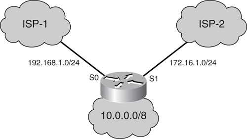
In [Figure 7-11](https://learning.oreilly.com/library/view/building-resilient-ip/1587052156/ch07.html#ch07fig11), a router is multihomed to the Internet by connecting through interface serial 0 to Internet service provider ISP-1, which has assigned the 192.168.1.0/24 address space. It is connected through interface serial 1 to ISP-2, which has assigned the address space 172.16.1.0/24. The LAN interface of the router is connected to the corporate inside network, which belongs to the 10.0.0.0/8 network. The requirement is that the same inside host should be translated to addresses assigned by the respective ISPs when traffic is forwarded through interface serial 0 or serial 1.
**Figure 7-11** _Multihomed NAT_
[Example 7-18](https://learning.oreilly.com/library/view/building-resilient-ip/1587052156/ch07.html#ch07ex18) shows the configuration for the border router.
**Example 7-18** _Sample Configuration For Multihomed NAT_
---
interface Ethernet0
ip address 10.1.1.1 255.0.0.0
ip nat inside
!This connects to the corporate network, designated as the NAT inside interface.
interface Serial0
ip address 192.168.1.1 255.255.255.252
ip nat outside
!This connects to the Internet through ISP-1, designated as the NAT outside
interface.
interface Serial1
ip address 172.16.1.1 255.255.255.252
ip nat outside
!This connects to the Internet through ISP-2, designated as the NAT outside
interface.
ip nat pool ISP-1 192.168.1.3 192.168.1.254 prefix-length 24
!This creates a pool by the name ISP-1, which contains addresses assigned by ISP-1.
ip nat pool ISP-2 172.16.1.3 172.16.1.254 prefix-length 24
!This creates a pool by the name ISP-2, which contains addresses assigned by ISP-2.
ip nat inside source route-map isp-1 pool ISP-1
!The preceding line configures Dynamic NAT mapping for the inside network
10.0.0.0/8 to a global address from the pool ISP-1 to be used for traffic matched
by the route-map isp-1.
ip nat inside source route-map isp-2 pool ISP-2
!The preceding line configures Dynamic NAT mapping for the inside network
10.0.0.0/8 to a global address from the pool ISP-2 to be used for traffic matched
by the route-map isp-2.
access-list 1 permit 10.0.0.0 0.255.255.255
!This ACL permits traffic from all hosts in the corporate network.
route-map isp-2 permit 10
match ip address 1
match interface Serial1
!This route-map matches all traffic matched by ACL 1 and going out of
interface serial 1. In other words, all traffic from the corporate network to the
Internet through ISP-2 is matched.
route-map isp-1 permit 10
match ip address 1
match interface Serial0
!This route-map matches all traffic matched by ACL 1 and going out of
interface serial 0. In other words, all traffic from the corporate network to the
Internet through ISP-1 is matched.
---
Another use of dynamic NAT with a route map is in the remote-access scenario with IP Security (IPsec). For example, you may be required to use NAT and IPsec together on a router to reach the Internet and a VPN site through the same interface. In this case, this feature can be used to selectively translate packets that are bound for the Internet and not translate traffic bound for the VPN site.
##### Static Mapping with Hot Standby Routing Protocol (HSRP) Support
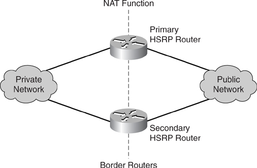
In previous examples, the NAT function has been performed by the border router, which is a single point of failure. One way to increase the availability of the border router performing NAT is to incorporate the function of HSRP.
As illustrated in [Figure 7-12](https://learning.oreilly.com/library/view/building-resilient-ip/1587052156/ch07.html#ch07fig12), when you combine the functions of HSRP and NAT, the introduction of the secondary router greatly enhances the availability of the NAT infrastructure. However, it is important to note that in this design, the two routers do not exchange states of the translations. Therefore, this design works with static mapping design only.
**Figure 7-12** _NAT with HSRP Support_
[Example 7-19](https://learning.oreilly.com/library/view/building-resilient-ip/1587052156/ch07.html#ch07ex19) illustrates the command for incorporating NAT with HSRP in the primary router.
**Example 7-19** _Configuring NAT with HSRP on the Primary Router_
---
Primary_Router#configure terminal
Primary_Router(config)#interface Serial0/0
Primary_Router(config-if)#ip address 64.104.85.1 255.255.255.252
Primary_Router(config-if)#ip nat outside
Primary_Router(config-if)#interface GigabitEthernet0/1
Primary_Router(config-if)#ip address 10.1.1.253 255.255.255.0
Primary_Router(config-if)#ip nat inside
Primary_Router(config-if)#standby ip 10.1.1.254
Primary_Router(config-if)#standby priority 100
Primary_Router(config-if)#standby name Border
Primary_Router(config-if)#standby preempt
Primary_Router(config-if)#standby track Serial0/0
Primary_Router(config-if)#exit
Primary_Router(config)#ip nat inside source static 10.1.1.1 64.104.85.101
---
[Example 7-20](https://learning.oreilly.com/library/view/building-resilient-ip/1587052156/ch07.html#ch07ex20) illustrates the corresponding configuration for the secondary router.
**Example 7-20** _Configuring NAT with HSRP on the Secondary Router_
---
Secondary_Router#configure terminal
Secondary_Router(config)#interface Serial0/0
Secondary_Router(config-if)#ip address 64.104.85.5 255.255.255.252
Secondary_Router(config-if)#ip nat outside
Secondary_Router(config-if)#interface GigabitEthernet0/1
Secondary_Router(config-if)#ip address 10.1.1.252 255.255.255.0
Secondary_Router(config-if)#ip nat inside
Secondary_Router(config-if)#standby ip 10.1.1.254
Secondary_Router(config-if)#standby priority 90
Secondary_Router(config-if)#standby name Border
Secondary_Router(config-if)#standby track Serial0/0
Secondary_Router(config-if)#exit
Secondary_Router(config)#ip nat inside source static 10.1.1.1 64.104.85.101
---
##### Stateful NAT
As you learned in the previous section, the introduction of a secondary router improves the availability of the NAT infrastructure. However, the lack of an exchange of states means only the static mapping method can be deployed. The introduction of stateful NAT solves this problem.
In stateful NAT, two or more routers function as a translation group. As in the HSRP approach, the primary router is in charge of forwarding and translating the IP addresses as required. In addition, it informs the secondary routers of the states of its translation activities. This enables the secondary routers to build the same translation tables. In the event that the primary router fails, the secondary routers take over the forwarding task with the information that is residing in the translation tables. In this case, traffic continues to flow because the same translation information is being used. The introduction of stateful NAT brings resiliency to dynamic NAT, and, of course, it continues to work for static NAT configuration.
The stateful NAT function is delivered in phases. In phase one, it supports applications that do not carry embedded IP addresses in the payload of the TCP or UDP packet. Therefore, Application Level Gateway (ALG) will not be supported in phase one. The following is a list of applications supported in phase one:
• Archie
• Finger
• HTTP
• ICMP
• Ping
• rcp, rlogin, and rsh
• TCP
• Telnet
The following applications are not supported in phase one:
• ALG
• FTP
• NetMeeting Directory
• Remote access server (RAS)
• SPA interface processor (SIP)
• Skinny
• Trivial File Transfer Protocol (TFTP)
• Asymmetrical routing
In phase two, the following application supports have been added:
• Voice over IP (VoIP)
• FTP
• DNS
• Asymmetrical routing
For a complete list of ALG support, refer to the Cisco IOS NAT Application Layer Gateway website at the following URL:
[http://www.cisco.com/en/US/tech/tk648/tk361/technologies_white_paper09186a00801af2b9.shtml](http://www.cisco.com/en/US/tech/tk648/tk361/technologies_white_paper09186a00801af2b9.shtml)
You can implement stateful NAT in two ways. One is by leveraging the HSRP method; the other is via a primary/secondary method.
###### Using the HSRP Method for Stateful NAT
In the HSRP method, the stateful NAT configuration is based on the usual HSRP configuration. The stateful NAT then makes use of the redundancy API built in to the Cisco IOS Software to perform its task. When this method is used, the primary and secondary NAT routers are elected according to the HSRP standby state.
[Example 7-21](https://learning.oreilly.com/library/view/building-resilient-ip/1587052156/ch07.html#ch07ex21) illustrates the configuration for the primary NAT router.
**Example 7-21** _Stateful NAT Based on HSRP Configuration on the Primary Router_
---
Primary_Router#configure terminal
Primary_Router(config)#interface serial0/0
Primary_Router(config)#ip address 64.104.85.1 255.255.255.252
Primary_Router(config-if)#ip nat outside
Primary_Router(config-if)#interface GigabitEthernet0/1
Primary_Router(config-if)#ip address 10.1.1.253 255.255.255.0
Primary_Router(config-if)#ip nat inside
Primary_Router(config-if)#standby ip 10.1.1.254
Primary_Router(config-if)#standby priority 100
Primary_Router(config-if)#standby name border
Primary_Router(config-if)#standby preempt
Primary_Router(config-if)#standby track Serial0/0
Primary_Router(config-if)#exit
Primary_Router(config)#ip nat pool public_pool 64.104.85.101 64.104.85.101 netmask
255.255.255.128
Primary_Router(config)#ip nat inside source list 100 pool public_pool overload
Primary_Router(config)#access-list 100 permit ip 10.1.1.0 0.0.0.255 any
Primary_Router(config)#ip nat stateful id 1
Primary_Router(config-ipnat-snat)#redundancy border
Primary_Router(config-ipnat-snat-red)#mapping-id 10
---
[Example 7-22](https://learning.oreilly.com/library/view/building-resilient-ip/1587052156/ch07.html#ch07ex22) illustrates the corresponding configuration for the secondary router.
**Example 7-22** _Stateful NAT Based on HSRP Configuration on the Secondary Router_
---
Secondary_Router#configure terminal
Secondary_Router(config)#interface serial0/0
Secondary_Router(config)#ip address 64.104.85.5 255.255.255.252
Secondary_Router(config-if)#ip nat outside
Secondary_Router(config-if)#interface GigabitEthernet0/1
Secondary_Router(config-if)#ip address 10.1.1.252 255.255.255.0
Secondary_Router(config-if)#ip nat inside
Secondary_Router(config-if)#standby ip 10.1.1.254
Secondary_Router(config-if)#standby priority 90
Secondary_Router(config-if)#standby name Border
Secondary_Router(config-if)#standby track Serial0/0
Secondary_Router(config-if)#exit
Secondary_Router(config)#ip nat pool Public_Pool 64.104.85.101 64.104.85.101
netmask 255.255.255.128
Secondary_Router(config)#ip nat inside source list 100 pool Public_Pool overload
Secondary_Router(config)#access-list 100 permit ip 10.1.1.0 0.0.0.255 any
Secondary_Router(config)#ip nat Stateful id 2
Secondary_Router(config-ipnat-snat)#redundancy Border
Secondary_Router(config-ipnat-snat-red)#mapping-id 10
---
###### Using the Primary/Secondary Method for Static NAT
In the primary/secondary method, you can explicitly specify the IP address of the primary and secondary routers (whereas in the HSRP method it was selected by the HSRP state).
[Example 7-23](https://learning.oreilly.com/library/view/building-resilient-ip/1587052156/ch07.html#ch07ex23) illustrates the configuration for the primary NAT router using the primary/secondary method.
**Example 7-23** _Stateful NAT Based on the Primary/Secondary Configuration on the Primary Router_
---
Primary_Router#configure terminal
Primary_Router(config)#interface serial0/0
Primary_Router(config-if)#ip address 64.104.85.1 255.255.255.252
Primary_Router(config-if)#ip nat outside
Primary_Router(config-if)#interface GigabitEthernet0/1
Primary_Router(config-if)#ip address 10.1.1.253 255.255.255.0
Primary_Router(config-if)#ip nat inside
Primary_Router(config-if)#standby ip 10.1.1.254
Primary_Router(config-if)#standby priority 100
Primary_Router(config-if)#standby name Border
Primary_Router(config-if)#standby preempt
Primary_Router(config-if)#standby track Serial0/0
Primary_Router(config-if)#exit
Primary_Router(config)#ip nat pool Public_Pool 64.104.85.101 64.104.85.101 netmask
255.255.255.128
Primary_Router(config)#ip nat inside source list 100 pool Public_Pool overload
Primary_Router(config)#access-list 100 permit ip 10.1.1.0 0.0.0.255 any
Primary_Router(config)#ip nat Stateful id 1
Primary_Router(config-ipnat-snat)#primary 10.1.1.253
Primary_Router(config-ipnat-snat-pri)#peer 10.1.1.252
Primary_Router(config-ipnat-snat-pri)#mapping-id 10
---
The **primary** command is used to identify the interface that will be used by the primary NAT router to communicate with the secondary router. The **peer** command is used to identify the partner.
[Example 7-24](https://learning.oreilly.com/library/view/building-resilient-ip/1587052156/ch07.html#ch07ex24) illustrates the corresponding configuration for the secondary NAT router using the primary/secondary method.
**Example 7-24** _Stateful NAT Based on a Primary/Secondary Configuration on the Secondary Router_
---
Secondary_Router#configure terminal
Secondary_Router(config)#interface serial0/0
Secondary_Router(config)#ip address 64.104.85.5 255.255.255.252
Secondary_Router(config-if)#ip nat outside
Secondary_Router(config-if)#interface GigabitEthernet0/1
Secondary_Router(config-if)#ip address 10.1.1.252 255.255.255.0
Secondary_Router(config-if)#ip nat inside
Secondary_Router(config-if)#standby ip 10.1.1.254
Secondary_Router(config-if)#standby priority 90
Secondary_Router(config-if)#standby name Border
Secondary_Router(config-if)#standby track Serial0/0
Secondary_Router(config-if)#exit
Secondary_Router(config)#ip nat pool Public_Pool 64.104.85.101 64.104.85.101
netmask 255.255.255.128
Secondary_Router(config)#ip nat inside source list 100 pool Public_Pool overload
Secondary_Router(config)#access-list 100 permit ip 10.1.1.0 0.0.0.255 any
Secondary_Router(config)#ip nat Stateful id 2
Secondary_Router(config-ipnat-snat)primary 10.1.1.252
Secondary_Router(config-ipnat-snat-pri)#peer 10.1.1.253
Secondary_Router(config-ipnat-snat-pri)#mapping-id 10
---
##### Limiting NAT Entries
By now, you have realized that one of the most important resources in the translation exercise is the global address pool. When the addresses in this address pool run out, new connections to the outside network may be denied. Therefore, the global address pool becomes a prime target for the DoS attacks. In addition, because NAT is a CPU-intensive operation, the operation itself may be a target, too. Numerous viruses, worms, and DoS attacks take out NAT service. Therefore, you must introduce mechanisms to protect this important part of the network.
Rate limiting the NAT operation is one such mechanism. This feature provides you with control over how the global address pool is utilized and limits the maximum number of concurrent NAT requests on the router.
[Example 7-25](https://learning.oreilly.com/library/view/building-resilient-ip/1587052156/ch07.html#ch07ex25) illustrates the command for limiting the maximum number of NAT entries to 200 on a router.
**Example 7-25** _Configuring Maximum Number of NAT Entries_
---
Router#configure terminal
Router(config)#ip nat translation max-entries 200
---
Note that in the command 200 is an arbitrary number and not a recommended configuration. You should determine the max entries based on your network requirement.
##### Multihoming with NAT
As described earlier in the section “[ISP-Level Redundancy](https://learning.oreilly.com/library/view/building-resilient-ip/1587052156/ch07.html#ch07sec2lev5),” acquiring multiple ISP connections is important for corporate networks that want redundant connectivity to the Internet. However, this may pose some technical challenges in terms of routing and addressing. Constructing a multihomed network is not as straightforward, because it involves some intricate addressing and routing issues. The best practices and details about the technicality of multihoming are documented in RFC 2008 and 2260.
RFC 2260 states an address allocation and routing formula for a multihomed network. Unfortunately, it suffers from drawbacks, such as requiring the corporate network to renumber its addresses when it comes time to change to another ISP. In addition, the method suggested also makes load balancing of the Internet traffic for the corporate network difficult because it lacks flexibility. However, some of these drawbacks may be overcome with the introduction of the NAT function. Multihoming with NAT is a complex operation that combines the operation of BGP with the NAT function.
[Figure 7-13](https://learning.oreilly.com/library/view/building-resilient-ip/1587052156/ch07.html#ch07fig13) illustrates the concept of _auto route injection_, which is described in RFC 2260. In [Figure 7-13](https://learning.oreilly.com/library/view/building-resilient-ip/1587052156/ch07.html#ch07fig13), the corporate network is served by two border routers, with each connecting to different ISPs. The two border routers, Border_A and Border_B, are connected to the border routers of the ISPs, ISP_A_Border and ISP_B_Border, respectively. Both Border_A and Border_B maintain an eBGP connection with their respective ISP’s border router, while they maintain an iBGP connection with each other. The iBGP connection is important because it ensures that traffic is not black-holed when there is a router failure. The global address prefix allocated by ISP A is denoted by Prefix_A, and the address prefix allocated by ISP B is denoted by Prefix_B.
**Figure 7-13** _Auto Route Injection Before Failure_
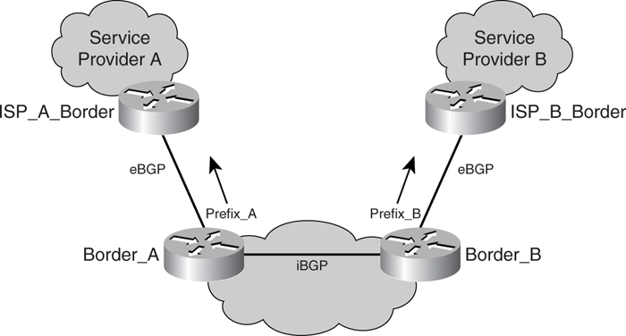
The idea behind auto route injection is such that when everything is in working order, both border routers, Border_A and Border_B, would only advertise the prefix that is allocated by the ISP to which they are connected. For example, Border_A will only advertise Prefix_A to ISP_A_Border, whereas Border_B will only advertise Prefix_B to ISP_B_Border. This is done when the set of routes Border_A receives from ISP_A_Border via the eBGP connection has a nonempty intersection with the set of routes it receives from Border_B via the iBGP connection. When the connection between Border_B and ISP_B_Border is broken, this intersection becomes empty. In this case, Border_A starts to advertise Prefix_B to ISP_A_Border. It continues to advertise Prefix_B for as long as the connection between Border_B and ISP_B_Border is broken, as illustrated in [Figure 7-14](https://learning.oreilly.com/library/view/building-resilient-ip/1587052156/ch07.html#ch07fig14).
**Figure 7-14** _Auto Route Injection After Failure_
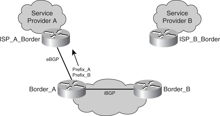
Besides running BGP to process the routes received from other peers, both the border routers, Border_A and Border_B, also run the NAT function. Running NAT in both the border routers means that the corporate network need not go through renumbering when there is a change in either of the ISPs. When there is a change in ISP, the inside address of the corporate network remains the same. The only reconfiguration that is required is the inside global address. This affects only the borders running NAT, which is a more manageable task.
When NAT is running in the border routers, they are configured with multiple pools of inside global addresses, which have been allocated by the various ISPs. An inside local address can be mapped to more than one inside global address from the multiple pools that have been created. This depends on which ISP the traffic is bound, based on the routing decision. This method of address translation is done via the route map option.
When you combine the feature of NAT and the functionality of the BGP protocol, the corporate network can increase the resiliency of its Internet connectivity.
#### Effects of NAT on Network and Applications
The basic concept of NAT may be just the translations of IP addresses and TCP port numbers. However, its application in the Internet module, or any other module, has a significant effect on the entire network. The following sections discuss important points that need your attention as you introduce NAT into a network.
##### Implications on TCP and ICMP Traffic
The function of NAPT allows for the mapping of multiple inside addresses to a single global address. This is done by including the TCP port number in the mapping decision, thus enabling a N:1 mapping. NAPT proves extremely useful for small remote office connections because service providers usually allocate only a single global address for such a network. With NAPT, all hosts within the inside network can establish connections to the outside network.
In NAPT, only TCP or UDP sessions are allowed and they must originate from the inside network. In some cases, an inbound session is required (for example, a DNS query). In this case, a statically configured well-known TCP port number may be required on the border router so that the query can be directed to a particular host within the inside network.
In addition to TCP or UDP sessions, you may have to take care of the ICMP messages. With the exception of the redirect message, the ICMP packets are translated in the same way as that of the TCP or UDP packets.
The complication with the NAPT setup is that because the global IP address and the WAN connectivity to the service provider usually share the same address, the border router has to differentiate traffic that is meant for itself from that of the inside network. The assumption here is that all inbound sessions are meant for the border router, unless the target service port has been statically mapped to a host within the inside network.
##### Application-Specific Gateways
The basic idea of NAT is to map the source or destination IP addresses in the IP packets so that connections can be established from the inside to the outside network. This operation is transparent to most applications except those that embed IP address information in the payload of the IP packet. One example of such an application is the FTP application. Because NAT only deals with the source or destination IP address in the IP packet, it does not take care of those embedded in the payload. Therefore, passing these applications through NAT will not work. ALGs are specially written code to handle such applications and they usually accompany the NAT feature. The FTP ALG, for one, is found in almost all NAT implementations.
The following types of ALGs are supported on the Cisco IOS Software:
• ICMP
• FTP PORT and PASV commands
• NetBIOS over TCP/IP (datagram, name, and session services)
• RealAudio
• CuSeeMe
• StreamWorks
• DNS A and PTR queries
• Netmeeting
• H.323v2-H.225/245 message types
• Session Initiation Protocol (SIP)
• Skinny Client Control Protocol (SCCP)
• Real Time Streaming Protocol (RTSP)
• VDOLive
• Vxtreme
• IP Multicast
• PPTP
• MPLS VPN (VPN routing and forwarding [VRF]-aware NAT)
• IPsec Encapsulating Security Payload (ESP) mode tunnels in PAT configuration
• SPI-matching—Multiple IPsec ESP mode tunnels
The significance of the ALG involvement in payload alteration means that the payload itself must not be encoded. Unless the ALG can decrypt the information, it will be rendered useless in this scenario and the application will break.
##### Effects on Voice over IP (VoIP) Traffic
Because VoIP traffic is becoming common in most networks, you must take care when the traffic is traversing through some NAT devices, especially firewalls. If you deploy a firewall with NAT features in a VoIP network, the firewall must have some additional features for the VoIP application to work. VoIP endpoints rely on signaling protocols to initiate a call. These protocols run on well-known port numbers, and, therefore, static pinholes can be created in the firewall that lies in the traffic path. However, the signaling protocols also carry information such as the IP address of the end point and the dynamic port number to be used. With the ability to inspect information deep into the signaling packet, the firewall will then open another pinhole for that dynamic port number. This new pinhole lasts as long as the duration of the conversation. For the firewall to perform this task, it needs the ALG for the signaling protocols.
After the signaling is done, the endpoints are ready to establish a connection. The voice stream is carried in RTP packets with the dynamically assigned port number. At the same time, the firewall also performs the necessary IP address translation for the RTP packets.
Obviously, if you want to deploy a VoIP application with firewall and NAT features, you must plan the design and configuration carefully. This is especially so when you have to consider the strict performance requirement of voice traffic. With the firewall and the NAT features in the path of the voice traffic, it is important that these do not affect the quality of the voice call, because implementing NAT may affect the router’s processing performance.
##### Effects on Router Performance
When the source IP or destination IP address within the IP packet needs to be changed, the router needs to recalculate the checksum in the IP packet. For TCP and UDP payload, the checksum within the TCP and UDP headers must be updated, too. Therefore, for both basic NAT and NAPT, the router needs to make modifications to the IP packets in several parts. And this has to be done on every single packet that traverses the router. Besides making the necessary changes, the router also needs to maintain the translation table for all the sessions. Thus, the NAT feature can be quite demanding on the CPU and memory resources.
Therefore, proper sizing of the border router needs to be done prior to turning on the NAT feature. When choosing the right border router, consider the bandwidth required and the number of sessions expected. Some of the latest router products from Cisco incorporate special ASIC to offload CPU-intensive functions, including NAT. These hardware-assisted NAT features certainly help in maintaining a healthy CPU situation. Products such as the Cisco 7304 series router with NSE-100 processor support NAT through the PXF ASIC. Alternatively, you should consider the ISR range of routers that support NAT without degradation in performance when sourcing for a border router.
##### Effects on Network Security
NAT provides a certain degree of security for the host residing in the inside network, because its true IP address is hidden from the outside network. It is more difficult to launch a direct attack on this host, because its address cannot be directly accessed from the Internet. However, this address-masking capability means that diagnosing legitimate application problems is more difficult. You must keep track of the translations, and determine whether it was the translation itself or the payload that caused a problem. In addition, in the event that a host from the inside network is launching an attack on some host residing in the outside network, it is hard to trace the troublemaker from the outside network.
Introducing the NAT feature is not a straightforward decision. Many aspects of the network, from hardware support to application performance, will be affected and must be carefully sorted out. However, if properly worked into the network from the early design stage, NAT can be a powerful tool in contributing to the resiliency of the network.
### Summary
The Internet module is responsible for connecting the entire network to the Internet. Because the Internet is used for business purposes, establishing Internet module redundancy is critical. Understanding the addressing schemes and routing policies in the Internet, and security practice, is a prerequisite to establishing a resilient design. This design is further supported by enhancements made to the BGP and NAT features within the IOS.
table of contents
search
Settings
[Chapter 6. Access Module](https://learning.oreilly.com/library/view/building-resilient-ip/1587052156/ch06.html)
Chapter 7. Internet Module
queue
Building Resilient IP Networks
[Chapter 8. WAN Module
](https://learning.oreilly.com/library/view/building-resilient-ip/1587052156/ch08.html)