[Skip to Content](https://learning.oreilly.com/library/view/building-resilient-ip/1587052156/ch08.html#main)
[](https://learning.oreilly.com/home/)
- Explore Skills
- Start Learning
- Featured
[Answers](https://learning.oreilly.com/answers2/)
Search for books, courses, events, and more
## Chapter 8. WAN Module
---
This chapter covers the following topics:
• [Leased Line](https://learning.oreilly.com/library/view/building-resilient-ip/1587052156/ch08.html#ch08sec1lev1)
• [SONET/SDH](https://learning.oreilly.com/library/view/building-resilient-ip/1587052156/ch08.html#ch08sec1lev2)
• [Resilient Packet Ring](https://learning.oreilly.com/library/view/building-resilient-ip/1587052156/ch08.html#ch08sec1lev3)
• [Dial Backup](https://learning.oreilly.com/library/view/building-resilient-ip/1587052156/ch08.html#ch08sec1lev4)
• [Virtual Private Network](https://learning.oreilly.com/library/view/building-resilient-ip/1587052156/ch08.html#ch08sec1lev5)
---
WAN connectivity is a key element in the resilient IP infrastructure. Most IP networks require some form of WAN connectivity to connect two or more location together. Hence, the robustness of the WAN connectivity is important.
WAN connectivity exists in many forms, including as a simple leased circuit between two offices that are located near each other, and long-haul submarine cable systems. In this chapter, you learn about popular choices of WAN connectivity available in the industry. You also look at what the issues are, both technically and operationally, to provide a resilient IP WAN infrastructure. However, in most contexts, the choice of WAN connectivity is usually determined by availability of service and economics. In some cases, a certain WAN connectivity option that is ideal for the deployment might not be available by the local provider of such a service. In other cases, an option might not be cost-effective.
In most cases of deployment, the final choice of WAN connectivity is a good balance of cost and availability of service. In some cases, a mixture of two of more connectivity options might increase network availability and reduce the cost of operations. For instance, your WAN connectivity might be a mixture of expensive leased line and IP tunnel going through the Internet. Cost for the IP tunnel via the Internet might be significantly cheaper than the leased line. It will be cost-effective to load share the traffic across both the leased line and IP tunnel to reduce the total cost of WAN connectivity. At the same time, it reduces dependency on a single service provider and technology.
### Leased Line
Leased line, or leased circuit in some cases, is the simplest form of WAN connectivity. Most service providers provide leased lined or leased circuit service to customers. Service providers provision the traffic for each of their customers in their backbone, and deliver the service to the customers with a dedicated physical circuit.
[Table 8-1](https://learning.oreilly.com/library/view/building-resilient-ip/1587052156/ch08.html#ch08tab01) summarizes the leased circuits typically available from a service provider.
**Table 8-1** _Various Leased Circuits Available_
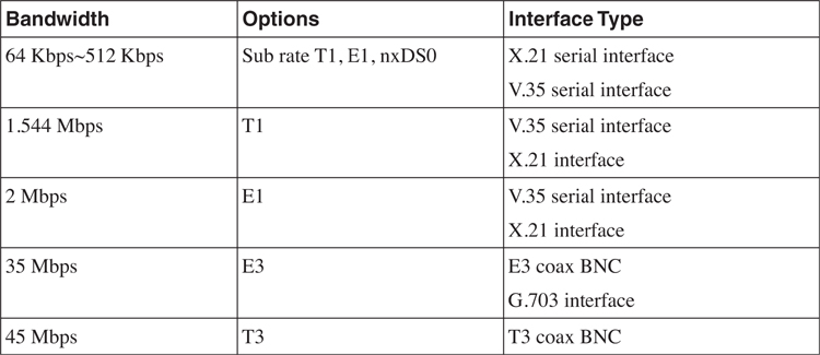
The choice of the leased circuit used depends on the network bandwidth that is required and the type of service available from the service provider.
#### Domestic Leased Circuit Versus International Private Leased Circuit
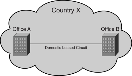
In general, leased circuit service can be divided into domestic leased circuit (DLC) or international private leased circuit (IPLC). _DLC_ is a term used by service providers to denote a leased circuit within a country, as shown in [Figure 8-1](https://learning.oreilly.com/library/view/building-resilient-ip/1587052156/ch08.html#ch08fig01).
**Figure 8-1** _Domestic Leased Circuit (DLC)_
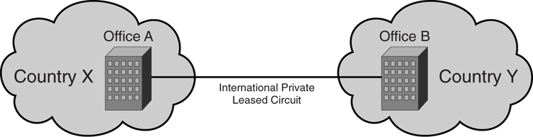
As opposed to DLC, IPLC is a leased line provided between countries. [Figure 8-2](https://learning.oreilly.com/library/view/building-resilient-ip/1587052156/ch08.html#ch08fig02) shows IPLC.
**Figure 8-2** _International Private Leased Circuit (IPLC)_
Major service providers with an international presence offer IPLC. In some cases, the user might choose to purchase a _half circuit_. The concept of half circuit is such that the user might want to purchase one end of the circuit from one service provider in one country and another end of the circuit from another service provider in another country. [Figure 8-3](https://learning.oreilly.com/library/view/building-resilient-ip/1587052156/ch08.html#ch08fig03) illustrates the concept of a half circuit.
**Figure 8-3** _Half Circuit_
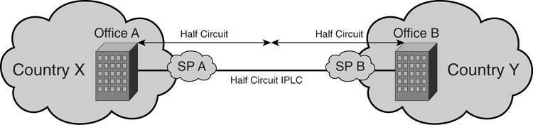
Half circuit is usually done either for cost reasons, or because the service provider within your country does not have the reach and capacity to provide the leased circuit to the target country.
#### Leased Circuit Encapsulation
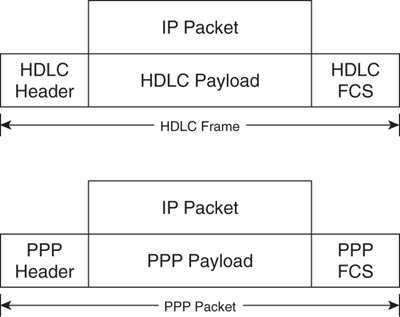
To send the IP traffic across a leased circuit, additional lower-layer protocols are used. Both High-Level Data Link Control (HDLC) and Point-to-Point Protocol (PPP) are popular WAN encapsulation protocols. The IP packet is data carried as a payload on either an HDLC frame or a PPP packet. [Figure 8-4](https://learning.oreilly.com/library/view/building-resilient-ip/1587052156/ch08.html#ch08fig04) illustrates an HDLC frame and a PPP packet.
**Figure 8-4** _Comparing HDLC and PPP_
As illustrated in [Figure 8-5](https://learning.oreilly.com/library/view/building-resilient-ip/1587052156/ch08.html#ch08fig05), connecting two routers via a leased line is straightforward.
**Figure 8-5** _One Leased Line Connecting Two Routers_

[Example 8-1](https://learning.oreilly.com/library/view/building-resilient-ip/1587052156/ch08.html#ch08ex01) shows the configurations required on Router A and Router B.
**Example 8-1** _Two Routers Connected via a Leased Line Configuration_
---
Router A
interface serial 0
ip address 1.1.1.1 255.255.255.0
no shutdown
Router B
interface serial 0
ip address 1.1.1.2 255.255.255.0
no shutdown
---
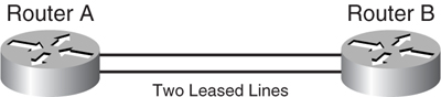
Traditionally, the leased circuit has always been treated as the “weakest link” in network design. The assumption is that a leased circuit will never be as reliable as a LAN connection. Therefore, one solution is to provision a second leased circuit to improve the resiliency of the WAN. It is a good idea to purchase the circuits from two or more providers when possible. Doing so improves resiliency by removing the dependency on a single provider, as illustrated in [Figure 8-6](https://learning.oreilly.com/library/view/building-resilient-ip/1587052156/ch08.html#ch08fig06).
**Figure 8-6** _Two Leased Lines Connecting Two Routers_
[Example 8-2](https://learning.oreilly.com/library/view/building-resilient-ip/1587052156/ch08.html#ch08ex02) shows the configuration for a dual-circuit design.
**Example 8-2** _Two Routers Connected via Two Leased Circuits_
---
Router A
interface serial 0
ip address 1.1.1.1 255.255.255.0
no shutdown
interface serial 1
ip address 1.1.2.1 255.255.255.0
no shutdown
Router B
interface serial 0
ip address 1.1.1.2 255.255.255.0
no shutdown
interface serial 1
ip address 1.1.2.2 255.255.255.0
no shutdown
---
The introduction of a secondary leased circuit to increase resiliency does present some interesting questions. For example, in the case of two or more leased lines between two routers, you must distribute the traffic across those multiple leased lines. You have two possible solutions to this problem:
• [Equal-cost load balancing](https://learning.oreilly.com/library/view/building-resilient-ip/1587052156/ch08.html#ch08sec3lev1)
• [Multilink Point-to-Point Protocol (MPPP)](https://learning.oreilly.com/library/view/building-resilient-ip/1587052156/ch08.html#ch08sec3lev2)
##### Equal-Cost Load Balancing
Equal-cost load balancing is an algorithm dealing with multiple routes to a common destination. These routes will have the same weight such that no route is more preferred. The router treats both routes as equal cost and performs load balancing between the two routes in an alternate fashion.
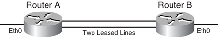
In [Figure 8-7](https://learning.oreilly.com/library/view/building-resilient-ip/1587052156/ch08.html#ch08fig07), traffic between the Ethernet interfaces of Routers A and B can be load balanced via the configuration shown in [Example 8-3](https://learning.oreilly.com/library/view/building-resilient-ip/1587052156/ch08.html#ch08ex03).
**Figure 8-7** _Equal-Cost Load Balancing_
**Example 8-3** _Equal-Cost Load Balancing for Two Routers_
---
Router A
Interface Ethernet 0
ip address 2.2.2.0 255.255.255.0
no shutdown
interface serial 0
ip address 1.1.1.1 255.255.255.0
no shutdown
interface serial 1
ip address 1.1.2.1 255.255.255.0
no shutdown
ip route 0.0.0.0 0.0.0.0 serial 0
ip route 0.0.0.0 0.0.0.0 serial 1
Router B
interface ethernet 0
ip address 2.2.3.0 255.255.255.0
no shutdown
interface serial 0
ip address 1.1.1.2 255.255.255.0
no shutdown
interface serial 1
ip address 1.1.2.2 255.255.255.0
no shutdown
ip route 0.0.0.0 0.0.0.0 serial 0
ip route 0.0.0.0 0.0.0.0 serial 1
---
##### Multilink Point-to-Point Protocol (MPPP)
As opposed to the equal-cost load balancing method, MPPP is a PPP feature when two or more PPP sessions are bonded together to form a single logical connection. From the router’s point of view, there is only one IP connection between the two routers. This is the main difference between the two methods.
Using [Figure 8-7](https://learning.oreilly.com/library/view/building-resilient-ip/1587052156/ch08.html#ch08fig07) as an example, the two leased circuits can be bonded via MPPP as shown in [Example 8-4](https://learning.oreilly.com/library/view/building-resilient-ip/1587052156/ch08.html#ch08ex04).
**Example 8-4** _MPPP Configuration for Two Routers_
---
Router A
Interface Ethernet 0
ip address 2.2.2.0 255.255.255.0
no shutdown
interface multilink1
ip address 1.1.1.1 255.255.255.0
ppp multilink
multilink-group 1
interface serial 0
encapsulation ppp
ppp multilink
multilink-group 1
interface serial 1
encapsulation ppp
ppp multilink
multilink-group 1
ip route 0.0.0.0 0.0.0.0 multilink1
Router B
interface ethernet 0
ip address 2.2.3.0 255.255.255.0
no shutdown
interface multilink1
ip address 1.1.1.2 255.255.255.0
ppp multilink
multilink-group 1
interface serial 0
encapsulation ppp
ppp multilink
multilink-group 1
interface serial 1
encapsulation ppp
ppp multilink
multilink-group 1
ip route 0.0.0.0 0.0.0.0 multilink1
---
There are a few advantages of using MPPP versus equal-cost load balancing. One key advantage of MPPP is the ability to perform fragmentation of frames and interleaving of frames. Fragmentation of frames enables large packets to be fragmented into a small enough size to satisfy the delay requirement of real-time traffic, especially voice. The interleaving feature provides a special transmit queue for the smaller delay-sensitive packets, enabling them to be sent earlier than the rest of the packets. However, MPPP requires more processing power from the router’s CPU, which makes it unsuitable for certain low-end routers. When using MPPP for voice, latency for both circuits has to be equal. If it is not, the packets might not arrive at the same time, which will cause the voice quality to suffer.
### SONET/SDH
Synchronous Optical Network (SONET)/Synchronous Digital Hierarchy (SDH) is a common technology used by service providers to offer circuits over an optical network. The SONET specification is defined by American National Standards Institute (ANSI), under ANSI T1.105, ANSI T1.106, ANSI T1.117, and Bellcore GR-253. SDH is defined by the International Telecommunication Union Telecommunication Standardization Sector (ITU-T). In general, SONET equipment is used in North America, and SDH is generally used in the rest of the world.
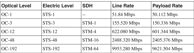
Both SONET and SDH are based on a similar frame structure. SONET uses a frame structure known as Synchronous Transport Signal (STS), but SDH uses a frame structure know as Synchronous Transport Module (STM). Speed-wise, a SONET OC-3 is similar to SDH STM-1, at 155 Mbps. SONET/SDH also uses multiplexing and demultiplexing technology to transport its payload. For that, multiple STS-1 signals can be multiplexed to form a single STS-3 signal. Likewise, multiple STM-4 signals can be multiplexed into a single STM-16 signal. [Table 8-2](https://learning.oreilly.com/library/view/building-resilient-ip/1587052156/ch08.html#ch08tab02) illustrates the various SONET/SDH speeds.
**Table 8-2** _SONET/SDH Speeds_
Although SONET and SDH are quite similar in nature, they have differences, such as the naming conventions used in both technologies. For example, SONET uses section, line, and path, whereas SDH uses path, multiplex section, and regenerator section. A detailed explanation of those terms is beyond the scope of this book.
A typical SONET/SDH network is built using optical fiber rings, as illustrated in [Figure 8-8](https://learning.oreilly.com/library/view/building-resilient-ip/1587052156/ch08.html#ch08fig08). A single SONET/SDH ring is built with two fiber rings to improve resiliency. The network can be made up of multiple rings. A SONET/SDH ADM (add/drop multiplexer) is used to multiplex multiple rings into a single ring.
**Figure 8-8** _Typical SONET/SDH Network_
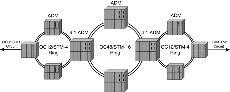
A typical service provider might build a main OC-48/STM-16 ring and extend it to multiple, smaller OC-12/STM-4 rings. Given that four OC-12/STM-4s can be multiplexed (muxed) into a single OC-48/STM-16, the service provider can build four smaller OC-12 rings. A customer circuit is provisioned on the ADM by demultiplexing on the OC-12 rings.
A OC-48/STM-16 ring can support four OC-12/STM-4 rings. One OC-12/STM-4 ring can then support four OC-3/STM-1 circuits. So, one OC-48/STM-16 ring can support 16 OC-3/STM-1 circuits. That does not sound like a large number. However, a single OC-3/STM-1 circuit can be demuxed into multiple DS-3 circuits and more T1 and E1 circuits.
In the next sections, you learn about various SONET/SDH framing and SONET/SDH multiplexing issues.
#### SONET/SDH Framing
A basic signal in SONET is OC-1 (Optical Channel level 1), or its electrical equivalent STS-1 (Synchronous Transport Signal level 1). The signal is organized in 9 rows and 90 columns of 8 bits (1 byte). This frame is then repeated at 8000 times in 1 second. Hence, the bandwidth will be 9 (rows) × 90 (columns) × 8000 (frame/sec) × 8 (bit) = 51.84 Mbps.
[Figure 8-9](https://learning.oreilly.com/library/view/building-resilient-ip/1587052156/ch08.html#ch08fig09) illustrates SONET framing.
**Figure 8-9** _SONET Framing_

The fields in the frame are as follows:
• **A1 and A2**—Frame start
• **J0**—Section trace
• **B1**—Section error monitoring
• **E1**—Local orderwire channels
• **F1**—Reserved
• **D1 to D12**—Data communication channels
• **H1 and H2**—Synchronous payload envelope (SPE) pointers
• **H3**—Pointer action byte
• **B2**—Line error monitoring
• **K1 and K2**—Signaling for protection of multiplex section
• **Z1 and Z2**—For future use
• **E3**—Allocated for express orderwire between line entities
• **J1**—Synchronous Transport Signal (STS) path trace
• **B3**—Path error monitoring
• **C2**—Signal label
• **G1**—Path status
• **F2**—Path user channel
• **H4**—Multiframe indication
• **Z3 and Z4**—Future use
• **N1**—Tandem connection maintenance
The upper three columns contain section overhead (SOH) information. The lower six contain line overhead information. The remaining 87 columns are used for user data and carrying the SPE (synchronous payload envelope). SPE contains the path overhead (POH) and the payload. The first row of line overhead contains a pointer to the first byte of SPE.
SONET/SDH can also be multiplexed together, as illustrated in [Figure 8-10](https://learning.oreilly.com/library/view/building-resilient-ip/1587052156/ch08.html#ch08fig10).
**Figure 8-10** _Multiplexing SONET_
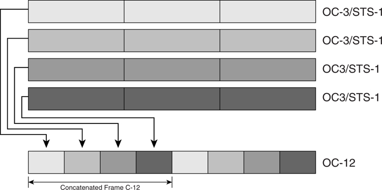
Multiple OC-3 can be multiplexed together to form an OC-12. OC-12c means concatenated payload; the virtual containers are not multiplexed.
#### PPP over SONET/SDH
In most cases, a SONET/SDH circuit provides a single serial bitstream. To carry IP traffic over a SONET/SDH circuit, HDLC and PPP are typically deployed.
From PPP’s point of view, SONET/SDH is just a full-duplex octet bitstream. PPP packets are carried using a SONET/SDH payload in a form of SPE or an SDH virtual container (VC). Likewise, HDLC frames are carried as a SONET/SDH payload.
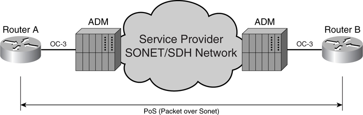
In [Figure 8-11](https://learning.oreilly.com/library/view/building-resilient-ip/1587052156/ch08.html#ch08fig11), the router in each site is physically connected to the ADM by the service provider. The service provider will provision the OC-3 circuits between the two sites. The router will be configured to use either PPP or HDLC framing to carry IP traffic.
**Figure 8-11** _PPP over SONET/SDH Circuit for Two Sites_
#### SONET/SDH Protection Switching
Most SONET/SDH networks are built using dual fiber rings in an active and protect operation. SONET/SDH offers protection switching in case of a failure in the fiber.
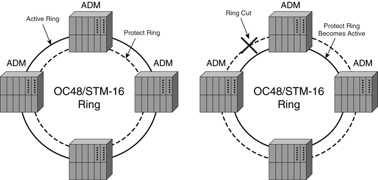
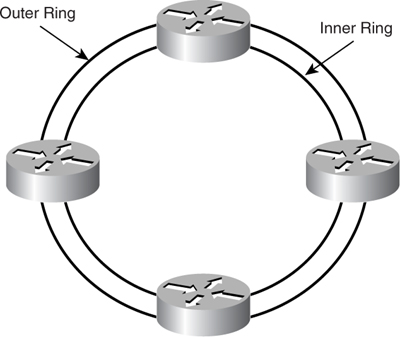
The topology of the ring can be in several forms. In its simplest form, known as _unidirectional self-healing ring_ (_USHR_), two fibers are used, as shown in [Figure 8-12](https://learning.oreilly.com/library/view/building-resilient-ip/1587052156/ch08.html#ch08fig12). The outer ring is the active ring, and the inner ring is the protect ring. In this scenario, all traffic uses the outer ring for transmission. However, during a fiber cut on the outer ring, as shown on the right of the diagram, SONET/SDH protection switching kicks in to make the inner ring the active ring. The switchover is made within 50 milliseconds (ms) of ring failure.
**Figure 8-12** _SONET/SDH Network Protection_
Another topology, bidirectional line switch ring (BLSR), can be built with two fibers. The difference between a USHR and BLSR is that the protection switching takes effect only on the segment when the fiber is broken. The rest of the ring segment continues to work normally.
Based on the same technology, linear automatic protection switching can be used to protect a link failure between the router and the SONET/SDH ADM.
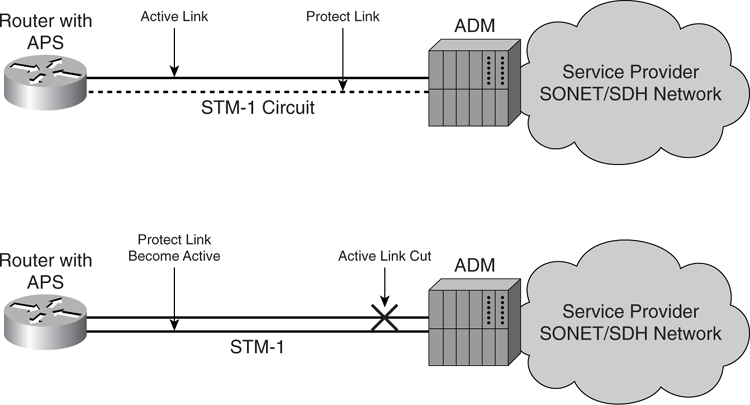
[Figure 8-13](https://learning.oreilly.com/library/view/building-resilient-ip/1587052156/ch08.html#ch08fig13) shows a router that supports SONET/SDH Automatic Protection Switching (APS). The router is configured with an active link and a protected link to the SONET/SDH ADM. If a link failure occurs on one of the links, SONET/SDH APS kicks in and failovers the circuit to the protected link. The failover time is less than 50 ms. APS within a router does not require Layer 3 routing to reconverge. APS can also be applied across two routers when one router will be a working router and another router will be a protect router. When a switchover is required for multiple router configuration, Layer 3 routing must reconverge.
**Figure 8-13** _SONET/SDH Protection Switching_
The advantage of such a configuration is that it protects against failure of the link to the SONET/SDH ADM. However, the effect of it is that the protection link will not be used unless a failover occurs. This incurs additional cost on the router port, and the general cost from the service provider to provide additional protection circuit is higher.
[Figure 8-14](https://learning.oreilly.com/library/view/building-resilient-ip/1587052156/ch08.html#ch08fig14) illustrates an example for a single router connected to a SONET ADM and running APS.
**Figure 8-14** _APS for a Single Router with an ADM_
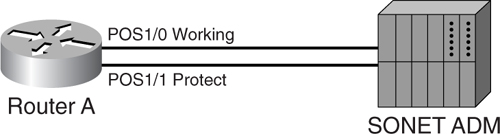
[Example 8-5](https://learning.oreilly.com/library/view/building-resilient-ip/1587052156/ch08.html#ch08ex05) shows the configuration for APS for a single router as illustrated in [Figure 8-14](https://learning.oreilly.com/library/view/building-resilient-ip/1587052156/ch08.html#ch08fig14).
**Example 8-5** _Configuration of Router A_
---
Router A
interface Loopback0
ip address 10.1.1.1 255.255.255.255
!
interface POS1/0
ip address 10.1.1.2 255.255.255.0
aps group 10
aps working 1
!
interface POS1/1
ip address 10.1.1.3 255.255.255.0
aps group 10
aps revert 1
aps protect 1 10.1.1.1
---
[Figure 8-15](https://learning.oreilly.com/library/view/building-resilient-ip/1587052156/ch08.html#ch08fig15) shows APS between two routers.
**Figure 8-15** _APS Between Two Routers with an ADM_
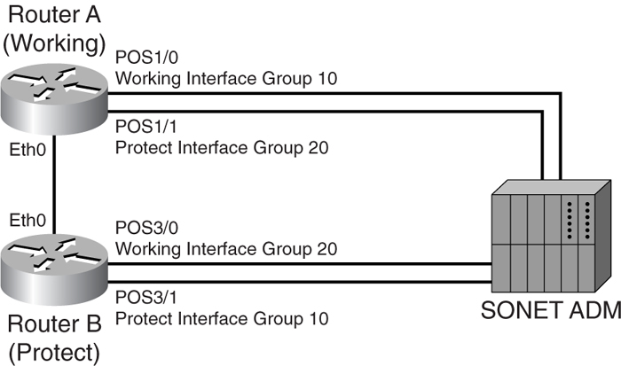
[Example 8-6](https://learning.oreilly.com/library/view/building-resilient-ip/1587052156/ch08.html#ch08ex06) shows the configuration of two routers with an ADM.
**Example 8-6** _Configuration of Two Routers with an ADM_
---
Router A (Working Router)
interface Loopback0
ip address 10.1.1.1 255.255.255.255
!
interface POS1/0
aps group 10
aps working 1
!
interface POS1/1
aps group 20
aps protect 1 10.1.1.2
Router B (Protect Router)
interface Loopback0
ip address 10.1.1.2 255.255.255.0
!
interface POS3/0
aps group 20
aps working 1
!
interface POS3/1
aps group 10
aps protect 1 10.1.1.1
!
---
By using SONET/SDH APS, you can increase the resiliency of the links of the router.
### Resilient Packet Ring
Resilient Packet Ring (RPR) technology is an emerging network architecture and technology based on-fiber ring similar to a SONET/SDH infrastructure.
RPR technology has a few key advantages:
• Offers resiliency to the existing fiber ring by having a protection switching mechanism similar to SONET/SDH.
• Supports multiple classes of service to offer traffic prioritization.
• Enables Multicast traffic to be carried efficiently without the need of packet replication.
Cisco Dynamic Packet Transport (DPT) technology is one such implementation of packet ring technology. Although RPR technology has been standardized in 2004, under the 802.17 working group, this section covers DPT rather than the 802.17 specifications.
Although DPT is a packet ring technology, Spatial Reuse Protocol is the underlying protocol that implements DPT. You will find that they might be used interchangeably.
#### DPT Architecture
Unlike a SONET/SDH infrastructure where there is a protection ring, which does not carry traffic unless there is a break in the working ring, DPT technology uses both fiber rings to carry traffic simultaneously. Hence, as compared with a SONET/SDH infrastructure, whereas an OC-12/STM-4 ring might just carry 622 Mbps of traffic, a corresponding DPT ring can carry 2 * 622 Mbps, or 1244 Mbps (1.2 Gbps).
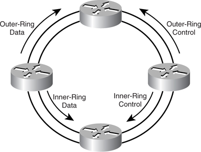
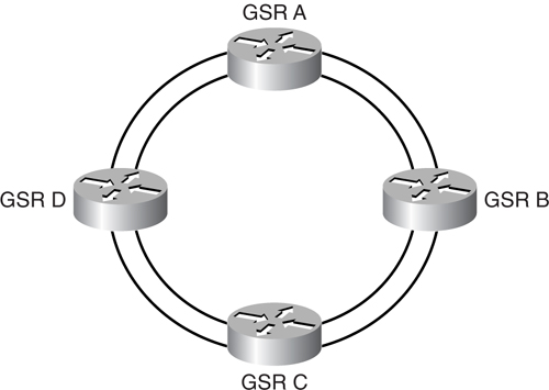
DPT uses dual counter-rotating rings with multiple nodes on the ring, as shown in [Figure 8-16](https://learning.oreilly.com/library/view/building-resilient-ip/1587052156/ch08.html#ch08fig16). Data and control traffic are carried over both rings in opposite directions. Topology information is carried via control traffic such that all the nodes on the ring have a complete view of the network topology with information of the existing nodes on the ring.
**Figure 8-16** _DPT with Four Routers_
As shown in [Figure 8-17](https://learning.oreilly.com/library/view/building-resilient-ip/1587052156/ch08.html#ch08fig17), the concept of having control traffic carried in the opposite direction of data traffic is such that, in case of a fiber break along the path, control traffic can be carried effectively to tell the corresponding node to “wrap” the ring by redirecting the packets from the inner ring to the outer ring depending on the direction of the ring. The protection mechanism allows traffic to be redirected, with little or no drop in packets.
**Figure 8-17** _Counter-Rotating Rings of DPT_
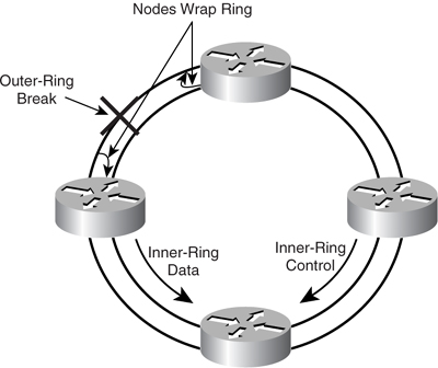
In [Figure 8-18](https://learning.oreilly.com/library/view/building-resilient-ip/1587052156/ch08.html#ch08fig18), when the outer rings break, the nodes closest to the break wrap the rings to redirect traffic and isolate the break. This protection switching is done within 50 ms, similar to SONET/SDH protection switching. When spatial reuse protocol (SRP) performs a switchover, no Layer 3 reconvergence occurs.
**Figure 8-18** _Breakage in DPT Four-Node Ring_
Shown in [Figure 8-19](https://learning.oreilly.com/library/view/building-resilient-ip/1587052156/ch08.html#ch08fig19), a DPT/SRP network can have multiple nodes on a single ring. Each node has two physical (PHY) interfaces and two data paths. Hence, this provides the necessary resiliency and causes the node to have two Media Access Control (MAC) addresses. When a node wants to send a packet to another node, it determines which ring has the shortest hop count to the destination based on the topology information discovered. When the packet arrives at the destination, it is removed from the ring. Therefore, bandwidth is only consumed on the span between the source node and the destination node.
**Figure 8-19** _SRP MAC Architecture_
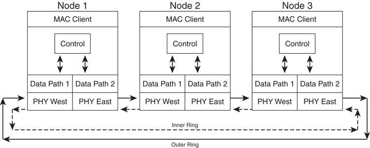
In the event of multicast traffic, the packet is inserted into the ring, and each node receives the similar packet, but the packet is not removed from the ring and instead continues to be forwarded to the next node. When the sender of the packet sees its packet arrive on itself, the packet is then stripped from the ring. The advantage of such an implementation is that each node is responsible for copying the packet to itself. No single node needs to do packet replication to other nodes on the ring. Therefore, it is scalable despite the number of nodes on the ring.
#### DPT/SRP Classes of Service
DPT/SRP offers two classes of service and fairness to the traffic on the ring:
• **High-priority service**—It is used to support high-priority service such as voice or video.
• **Low-priority service**—It is used for best-effort types of service.
The next sections describe SRP queuing and the fairness algorithm.
##### SRP Queuing
[Figure 8-20](https://learning.oreilly.com/library/view/building-resilient-ip/1587052156/ch08.html#ch08fig20) shows the general concept of how the various queues work. An RPR node typically has six different queues:
• Two queues to receive traffic for high-priority and low-priority service:
—High-priority RX queue
—Low-priority RX queue
• Two queues for adding traffic as either high priority or low priority:
—High-priority TX queue
—Low-priority TX queue
• Two transit queues:
—High-priority transit queue
—Low-priority transit queue
**Figure 8-20** _0RPR Fairness and Queuing on a Single Node_
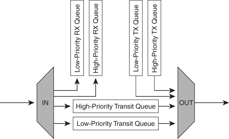
When packets must be transmitted into the ring, they are typically classified by the routers to determine the priority level and added into the respective queue to be added into the ring. When a packet arrives at the ring with a destination address of the node, it is sent to the respective receive queue to be sent to other interfaces in the router.
Transit queues are queues to hold traffic that goes through the node to another node on the ring.
##### SRP Fairness Algorithm
SRP offers a fairness algorithm that ensures priority to the traffic on the ring. Transmission scheduling is done in this order, from high priority to low priority:
**1** High-priority transmit (add)
**2** High-priority transit
**3** Low-priority transmit (add)
**4** Low-priority transit
When there is congestion, feedback control messages are sent to the neighboring node to throttle down the traffic.
#### RPR Standards
In 2000, the IEEE 802.17 Resilient Packet Ring working group was started as a unit under the IEEE 802 LAN/MAN working group. The 802.17 working group was formed with the objective to standardize on the RPR ring type of technology.
#### Differences Between 802.17 and DPT/SRP
Although both the 802.17 specification and DPT/SRP are similar as packet ring technologies, the two standards do differ.
In terms of class of service, DPT/SRP defines two classes of service: high priority and low priority. 802.17 defines three class of service: Class A, B, and C. 802.17 Class A service is a high-priority service. Class B service has a lower priority than Class A service, and Class C is a best-effort service. 802.17 Class A service is similar to DPR/SRP high-priority service. However, in DPT/SRP, there is not a concept of Class B service. DPT/SRP low priority is the best fit for Class B and Class C service combined.
Although the current Cisco implementation of DPT/SRP uses an OC-12 to OC-192 physical interface, the RPR specification allows the use of SONET/SDH interfaces and Gigabit Ethernet (GE) interfaces.
Cisco DPT/SRP requires the ring speed to be similar throughout all the nodes. So, if the DPR/SRP ring is OC-12, all the interfaces between all the nodes have to be OC-12. RPR does not have that requirement. One segment of the ring can be OC-12 and another segment can be OC-48. However, mixing interface speeds on the same ring has to be handled with care.
The RPR technology may sound complex with counter-rotating rings and SONET/SDH framing. Contrary to what it seems, the configuration for RPR on the Cisco router is straightforward. [Example 8-7](https://learning.oreilly.com/library/view/building-resilient-ip/1587052156/ch08.html#ch08ex07) shows the simple configurations for a four-node DPT/SRP ring, as illustrated in [Figure 8-21](https://learning.oreilly.com/library/view/building-resilient-ip/1587052156/ch08.html#ch08fig21).
**Figure 8-21** _DPT/SRP Dual Ring with Four Routers_
**Example 8-7** _Configuration Example of Four-Router DPR/SRP Ring_
---
GSR A Configuration
GSR A:
hostname GSR-A
!
interface Loopback0
ip address 10.0.0.1 255.255.255.255
!
interface SRP1/0
ip address 10.10.10.1 255.255.255.192
!
router ospf 100
network 10.10.10.0 0.0.0.255 area 1
network 10.0.0.1 0.0.0.0 area 0
auto-cost reference-bandwidth 2488
GSR B:
hostname GSR-B
!
interface Loopback0
ip address 10.0.0.2 255.255.255.255
!
interface SRP1/0
ip address 10.10.10.2 255.255.255.192
!
router ospf 100
network 10.10.10.0 0.0.0.255 area 1
network 10.0.0.1 255.255.255.255 area 0
GSR C:
hostname GSR-C
!
interface Loopback0
ip address 10.0.0.3 255.255.255.255
!
interface SRP1/0
ip address 10.10.10.3 255.255.255.192
!
router ospf 100
network 10.10.10.0 0.0.0.255 area 1
network 10.0.0.1 255.255.255.255 area 0
GSR D:
hostname GSR-D
!
interface Loopback0
ip address 10.0.0.4 255.255.255.255
!
interface SRP1/0
ip address 10.10.10.4 255.255.255.192
!
router ospf 100
network 10.10.10.0 0.0.0.255 area 1
network 10.0.0.1 255.255.255.255 area 0
---
Although the DPT technology is most commonly used in a WAN deployment, it can be used in the data center, too. DPT/SRP interfaces are available in servers from vendors. This provides for both performance and resiliency, because both the interfaces are capable of transmitting traffic, as well as SDH-like protection for the IP connectivity.
### Dial Backup
To achieve a resilient IP network design, you can sometimes use more than one leased circuit for redundancy. However, this solution may not make financial sense. In that case, a dial backup is one good option. Dial backup is also known as an on-demand circuit, and its concept is illustrated in [Figure 8-22](https://learning.oreilly.com/library/view/building-resilient-ip/1587052156/ch08.html#ch08fig22).
**Figure 8-22** _Two Routers Using ISDN as Backup_
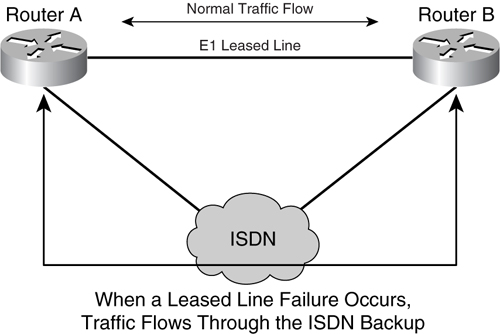
In [Figure 8-22](https://learning.oreilly.com/library/view/building-resilient-ip/1587052156/ch08.html#ch08fig22), under normal usage, traffic is carried across the E1 leased line between the two routers. Upon a failure of the leased line, the routers automatically dial up the neighboring router via an Integrated Service Digital Network (ISDN) connection. Whereas a traditional dial-up connection generally uses a copper phone line with an analog dial-up modem with up to 56 Kbps of bandwidth, an ISDN provides a digital dial-up line without the use of a modem.
Typically, there are two types of ISDN:
• ISDN Basic Rate Interface (BRI) provides 2B+1D channels; that is, two B channels of 64 kbps, and 1 D channel of 16 kbps. The B channels carry data, and the D channel is used for controling and signaling information. Because each B channel provides 64 Kbps, an ISDN BRI can carry 128 Kbps of data.
• ISDN Primary Rate Interface (PRI) depends on the physical line interface. In the United States, it is typically a T1 interface, which provides 23B+1D. However, in other parts of the world, it is usually an E1 interface, which provides 30D + a 64-Kbps D channel.
You can implement a dial backup solution in a few ways. The simplest way is to use a floating static route. A floating static route is a method of having a static route added to the neighboring router with a higher distance via the ISDN interfaces. Under a steady-state operation, the route via the serial interface is the preferred one. Upon a failure, the serial interface is marked as down, and the associated static route will not exist. Hence, the static route with the higher distance via the ISDN interface is used, as illustrated in [Figure 8-23](https://learning.oreilly.com/library/view/building-resilient-ip/1587052156/ch08.html#ch08fig23).
**Figure 8-23** _Floating Static Route_
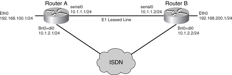
In [Figure 8-23](https://learning.oreilly.com/library/view/building-resilient-ip/1587052156/ch08.html#ch08fig23), Router A has an E1 leased line to Router B using a serial interface. In addition, Router A has an ISDN BRI to provide a backup interface. Router A has two static routes to reach the Router B Ethernet interface. The static route with a default cost routes the traffic using the serial interface, IP route 192.168.200.0/24 10.1.1.2, and the floating static route that has a higher distance of 100 will route using the ISDN BRI interface, IP route 192.168.200.0/24 10.1.2.2 100.
[Example 8-8](https://learning.oreilly.com/library/view/building-resilient-ip/1587052156/ch08.html#ch08ex08) shows the necessary configuration.
**Example 8-8** _Static Route Configuration_
---
Router A
hostname routerA
!
username routera password 0 <password>
!
isdn switch-type basic-net3
!
!
interface ethernet0
ip address 192.168.100.1 255.255.255.0
!
interface Serial0
ip address 10.1.1.1 255.255.255.0
!
interface BRI0
no ip address
encapsulation ppp
load-interval 30
dialer pool-member 1
isdn switch-type basic-net3
ppp authentication chap
!
interface Dialer0
ip address 10.1.2.1 255.255.255.0
encapsulation ppp
dialer pool 1
dialer remote-name routera
dialer string 1001
dialer-group 1
no cdp enable
ppp authentication chap
!
ip classless
ip route 192.168.200.0 255.255.255.0 10.1.1.2
ip route 192.168.200.0 255.255.255.0 10.1.2.2 100
!
dialer-list 1 protocol ip permit
!
end
Router B
hostname routerB
!
username routerb password 0 <password>
!
isdn switch-type basic-net3
!
!
interface ethernet0
ip address 192.168.200.1 255.255.255.0
!
interface Serial0
ip address 10.1.1.2 255.255.255.0
!
interface BRI0
no ip address
encapsulation ppp
load-interval 30
dialer pool-member 1
isdn switch-type basic-net3
ppp authentication chap
!
interface Dialer0
ip address 10.1.2.2 255.255.255.0
encapsulation ppp
dialer pool 1
dialer remote-name routerb
dialer string 1002
dialer-group 1
no cdp enable
ppp authentication chap
!
ip classless
ip route 192.168.100.0 255.255.255.0 10.1.1.1
ip route 192.168.100.0 255.255.255.0 10.1.2.1 100
!
dialer-list 1 protocol ip permit
!
end
---
As shown in [Example 8-8](https://learning.oreilly.com/library/view/building-resilient-ip/1587052156/ch08.html#ch08ex08), Cisco IOS uses a dialer interface to trigger the actual dial-up. The dialer interface is configured with the remote name to identity itself as the correct router. The dialer interface is configured with the dialer string that specified the number to dial.
### Virtual Private Network (VPN)
Service providers in various parts of the world are pushing Virtual Private Network (VPN) services in various ways as lower-cost but effective WAN connectivity. VPN is a general concept to run a private network over a public network infrastructure. You can purchase a VPN service from your service provider, and the service provider is responsible for setting up the tunnel for you, such as Multiprotocol Label Switching (MPLS)-VPN. You can also build your own network using existing technology to do either a Layer 3 tunnel or Layer 2 tunnel.
A Layer 3 tunnel enables you to transport Layer 3 packets, such as, IP over another IP network. The carrying of an IP packet as a payload on another IP packet is essentially an IP tunnel.
A Layer 2 tunnel offers even greater flexibility by transporting Layer 2 packets over an IP network. The Layer 2 packet can be a serial HDLC frame or an Ethernet frame and can be transported over the IP network.
In this section, you learn about the following technologies:
• Layer 3 tunnel in the form of an IP tunnel
• Layer 2 tunnel using L2TPv3
• MPLS-VPN
#### IP Tunnel
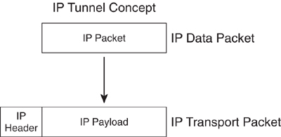
IP tunnels transport IP packets as data payload in another IP packet. A few technologies accomplish this functionality—namely, IP in IP tunneling and Generic Routing Encapsulation (GRE). IP in IP tunneling is described in RFC 1853, and GRE is described in RFC 2784.
As shown in [Figure 8-24](https://learning.oreilly.com/library/view/building-resilient-ip/1587052156/ch08.html#ch08fig24), an IP connection can be used as a transport layer for another IP packet.
**Figure 8-24** _IP Tunnel_
As illustrated in [Figure 8-25](https://learning.oreilly.com/library/view/building-resilient-ip/1587052156/ch08.html#ch08fig25), you might have two sites in remote locations or even located in different countries. Although IPLC will be expensive across two countries, there is an option to use an IP tunnel. Each local office can purchase an Internet transit service from the local Internet service provider (ISP). In this example, Site A is connected to its local ISP A, and Site B is connected to its local ISP B. Although the ISPs are connected via the Internet, you can set up an IP tunnel between the two sites. From a cost perspective, instead of purchasing an IPLC, the circuit can now be a virtual DLC, which is significantly cheaper.
**Figure 8-25** _IP Tunnel over Internet_
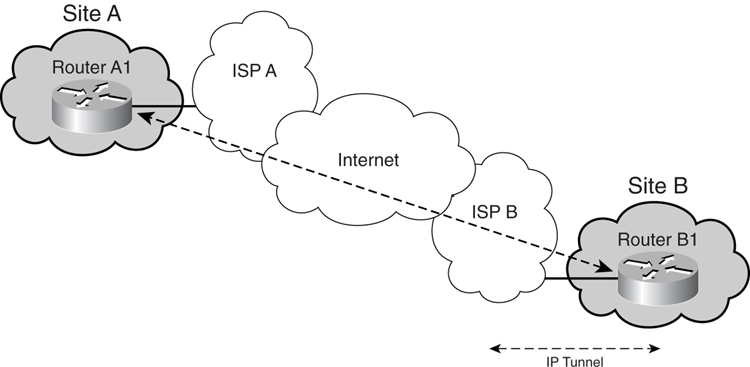
However, depending on the service level agreement given by the local ISP, the ISP might not guarantee the quality of Internet connectivity. Therefore, it is always wise to check out the quality level of the service offered by the ISP before committing to such an implementation as the primary WAN connectivity option.
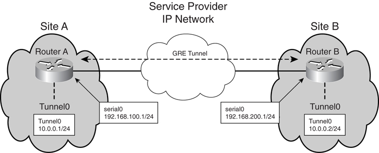
As illustrated in [Figure 8-26](https://learning.oreilly.com/library/view/building-resilient-ip/1587052156/ch08.html#ch08fig26), the IP tunnel can be a very simple setup using GRE. There are two sites, Site A and Site B, connected by an IP service from a service provider. Each site’s router, Router A and Router B, is connected to the service provider individually using a serial interface. A GRE tunnel is set up between the two routers, and a default route is statically defined at each end of the tunnel.
**Figure 8-26** _IP Tunnel Deployment_
[Example 8-9](https://learning.oreilly.com/library/view/building-resilient-ip/1587052156/ch08.html#ch08ex09) shows a sample configuration for the IP tunnel.
**Example 8-9** _IP Tunnel Configuration_
---
Router A
!
interface serial 0
ip address 192.168.100.1
!
interface Tunnel0
ip address 10.0.0.1 255.255.255.0
tunnel source 192.168.100.1 255.255.255.0
tunnel destination 192.168.200.1
tunnel mode gre
!
! route tunnel destination using serial 0
!
ip route 192.168.200.0 255.255.255.0 serial 0
!
! route the rest of the traffic using tunnel interface
!
ip route 0.0.0.0 0.0.0.0 tunnel0
Router B
!
Interface serial 0
Ip address 192.168.200.1 255.255.255.0
!
interface Tunnel0
ip address 10.0.0.2 255.255.255.0
tunnel source 192.168.200.1
tunnel destination 192.168.100.1
tunnel mode gre
!
! route tunnel destination using serial 0
!
ip route 192.168.100.0 255.255.255.0 serial 0
!
! route the rest of the traffic using tunnel interface
!
ip route 0.0.0.0 0.0.0.0 tunnel0
---
Note
IP in IP tunneling is similar to a GRE tunnel. To use IP in IP tunneling, just change the command from **tunnel mode gre** to **tunnel mode ipip**.
Tunnel interfaces behave very much like an ordinary serial interface. It is also possible to run a routing protocol on it, instead of using a static route as shown. However, to prevent routing loops, it is a good idea to put an explicit static route to the tunnel destination.
When an IP packet is carried over a tunnel interface, the packet size increases with the additional overhead of the tunnel header. The increase in size might exceed the MTU (maximum transfer unit) of the given physical interface. When that happens, the router drops the packet and sends an “ICMP Destination Unreachable” message with the flag “fragmentation needed and DF set” to the sender. If Internet Control Message Protocol (ICMP) is not blocked, the ICMP message arrives at the sender and the sender must fragment the packet and resend it at a small size. However, if ICMP is blocked along the way, the Destination Unreachable message might not reach the sender, and the result is that the packet will be silently dropped.
One solution is to run an MTU path discovery on the tunnel interface with the command **tunnel path-mtu-discovery**, whereby the router will automatically reduce the MTU size of the GRE tunnel when it sees an “ICMP Destination Unreachable” message with the flag “fragmentation needed and DF set.” Another solution is to manually reduce the size of the MTU on the interface itself, to force the IP packet to fragment before it reaches the tunnel interface.
#### L2TPv3
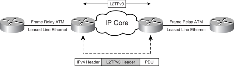
Layer 2 Tunnel Protocol (L2TP) is a technology to transport PPP packets over an IP network. It is defined in RFC 2661. L2TP version 3 (L2TPv3) is the standardized technology to carry any Layer 2 frame, such as a serial HDLC or Ethernet frame, over an IP network.
[Figure 8-27](https://learning.oreilly.com/library/view/building-resilient-ip/1587052156/ch08.html#ch08fig27) illustrates the concept of L2TPv3.
**Figure 8-27** _L2TPv3_
##### L2TPv3 Deployment
Although some service providers provide Ethernet or serial HDLC service using L2TPv3 technology, this section assumes that you will be implementing L2TPv3 yourself. Because the key advantage of L2TPv3 is the ability to transport Layer 2 frames, the deployment example in this section is based on transporting both Ethernet frames and serial HDLC frames.
The ability to transport Ethernet frames enables you to connect Ethernet switches together using a standard trunking protocol, such as Inter-Switch Link (ISL) or 802.1q. Although this simplifies the network design, take care to watch for broadcast traffic between the sites. This is especially so if the bandwidth of the IP connection between the two sites is limited.
In [Figure 8-28](https://learning.oreilly.com/library/view/building-resilient-ip/1587052156/ch08.html#ch08fig28), there are two sites in the network, Site A and Site B. Each site has a router that connects to the service provider’s IP network, known as Router A2 in Site A and Router B2 in Site B. This can be a router that subscribes to an IP transit service or Internet service from the service provider.
**Figure 8-28** _Deploying L2TPv3 on Two Sites_
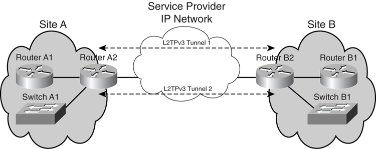
Within the network in each site, there is also one router (A1 in Site A) and one switch (A1 in Site A). These are the router and switch to which the rest of the systems connect.
Router A2 and Router B2 provide and maintain the L2TPv3 connection between the two sites. Two L2TPv3 sessions will be created: one to transport Ethernet frames and the other to transport serial HDLC frames.
[Example 8-10](https://learning.oreilly.com/library/view/building-resilient-ip/1587052156/ch08.html#ch08ex10) shows the configuration of Router A2 at Site A and the configuration of Router B2 at site B.
**Example 8-10** _Configuration Example of Router A2 in Site A_
---
Router A2
!
l2tp-class l2tp-defaults
retransmit initial retries 30
cookie-size 8
!
! pseudowire class for ethernet
!
pseudowire-class ether-pw
encapsulation l2tpv3
protocol none
ip local interface serial 0/0
!
! pseudowire class for HDLC
!
pseudowire-class hdlc-pw
encapsulation l2tpv3
protocol none
ip local interface serial 0/0
!
! 2M leased line to the service provider
!
Interface serial 0/0
ip address 192.168.100.1 255.255.255.0
!
! Create a L2TPv3 tunnel for the Ethernet interface
!
interface Ethernet 0/0
xconnect 192.168.200.1 100 encapsulation l2tpv3 manual pw-class ether-pw
l2tp id 200 100
l2tp cookie local 4 54321
l2tp cookie remote 4 12345
l2tp hello l2tp-defaults
!
! Create a L2TPv3 tunnel for the Serial interface
!
interface serial 1/0
xconnect 192.168.200.1 101 encapsulation l2tpv3 manual pw-class hdlc-pw
l2tp id 201 101
l2tp cookie local 4 54321
l2tp cookie remote 4 12345
l2tp hello l2tp-defaults
!
! default route to the service provider
!
ip route 0.0.0.0 0.0.0.0 192.168.100.2
Router B2
!
l2tp-class l2tp-defaults
retransmit initial retries 30
cookie-size 8
!
! pseudowire class for ethernet
!
pseudowire-class ether-pw
encapsulation l2tpv3
protocol none
ip local interface serial 0/0
!
! pseudowire class for HDLC
!
pseudowire-class hdlc-pw
encapsulation l2tpv3
protocol none
ip local interface serial 0/0
!
! 2M leased line to the service provider
!
Interface serial 0/0
ip address 192.168.200.1 255.255.255.0
!
! Create a L2TPv3 tunnel for the Ethernet interface
!
interface Ethernet 0/0
xconnect 192.168.100.1 100 encapsulation l2tpv3 manual pw-class ether-pw
l2tp id 100 200
l2tp cookie local 4 12345
l2tp cookie remote 4 54321
l2tp hello l2tp-defaults
!
! Create a L2TPv3 tunnel for the Serial interface
!
interface serial 1/0
xconnect 192.168.100.1 101 encapsulation l2tpv3 manual pw-class hdlc-pw
l2tp id 101 201
l2tp cookie local 4 12345
l2tp cookie remote 4 54321
l2tp hello l2tp-defaults
!
! default route to the service provider
!
ip route 0.0.0.0 0.0.0.0 192.168.200.2
---
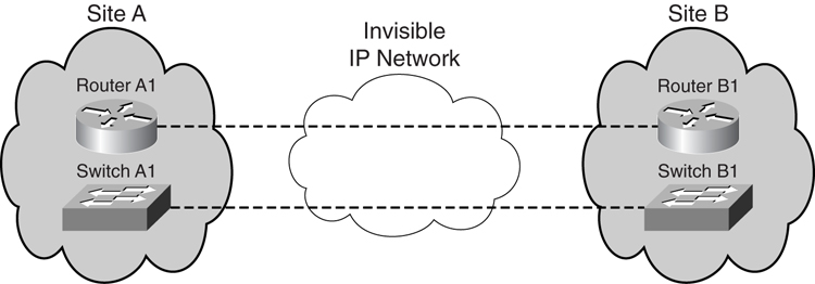
Although the complication of setting up a L2TPv3 tunnel resides within Router A2 and Router B2, from Router A1’s and B1’s point of view, they see each other as directly connected via the serial interface. Likewise, from switch A1’s and B1’s point of view, they see themselves as connected via a simple Ethernet interface, as illustrated in [Figure 8-29](https://learning.oreilly.com/library/view/building-resilient-ip/1587052156/ch08.html#ch08fig29).
**Figure 8-29** _View from End Nodes of L2TPv3_
[Example 8-11](https://learning.oreilly.com/library/view/building-resilient-ip/1587052156/ch08.html#ch08ex11) shows the configurations required for Router A1 and B1. Notice that the configuration is straightforward.
**Example 8-11** _End Nodes Configuration for L2TPv3_
---
Router A1
interface serial 0
ip address 192.168.100.1 255.255.255.0
Router B1
interface serial 0
ip address 192.168.100.2 255.255.255.0
---
Notice also that the IP addresses can be similar to that of Router A2’s and Router B2’s serial interfaces. The reason for this is that Router A1 and Router B1 only see each other via the tunnel. Whatever has been configured in the network in between them is invisible. [Example 8-12](https://learning.oreilly.com/library/view/building-resilient-ip/1587052156/ch08.html#ch08ex12) shows the configuration for the switches.
**Example 8-12** _Switch Configuration for L2TPv3_
---
Switch A1
interface FastEthernet 0/1
switchport trunk encapsulation dot1q
switchport mode dynamic desirable
Switch B1
interface FastEthernet 0/1
switchport trunk encapsulation dot1q
switchport mode dynamic desirable
---
#### MPLS-VPN
Multiprotocol Label Switching (MPLS) complements IP routing technology by introducing the concept of label switching on top of the regular IP destination routing. The MPLS technology prepends labels to IP packets. A separate forwarding table is also built, and traffic forwarding relies on labels rather than on normal routing.
There are a few key features of MPLS in addition to top of IP routing technology—namely, MPLS-VPN (virtual private network), traffic engineering (TE), and quality of service (QoS). This section only focuses on MPLS-VPN.
MPLS-VPN enables the creation of a VPN on top of an existing MPLS network. Although there is recent development to create both Layer 2 and Layer 3 VPNs, this section focuses only on Layer 3 VPNs.
Although many service providers offer MPLS-VPN as an alternative WAN connectivity for an IP network, the key advantage for MPLS-VPN is the ability to create VPNs with multiple sites and with the possibility of multiple physical links.
Shown in [Figure 8-30](https://learning.oreilly.com/library/view/building-resilient-ip/1587052156/ch08.html#ch08fig30), a router sitting at the edge of an MPLS network is known as a _label edge router_ (_LER_). The LER receives packets from an external normal IP router and then labels the IP packet with an MPLS label and forwards it into the MPLS network. At the heart of the MPLS network is the label switch router (LSR). When an LSR sees a labeled packet, it performs label swapping and forwards the packet to the next LSR, until it reaches the desired destination, which is another LER. The term _label switched path_ (LSP) is used to describe the path taken by the packets to traverse the network using MPLS label swapping.
**Figure 8-30** _MPLS Architecture_
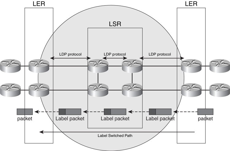
All the routers within an MPLS network run a common IGP, either OSPF or IS-IS. The router builds a routing table using this routing protocol and then uses the routing table to build a label forwarding table. A forwarding equivalence class (FEC) is used to describe a group of IP packets forwarded over the same path. The LSRs use Label Distribution Protocol (LDP) to exchange label information with each other. Hence, in a MPLS network, forwarding decisions are based on labels rather than routing information. However, routing information provided by the IGP protocol, OSPF or IS-IS, constructs the label forwarding table.
The MPLS-VPN feature enables the creation of VPNs within the MPLS network. [Figure 8-31](https://learning.oreilly.com/library/view/building-resilient-ip/1587052156/ch08.html#ch08fig31) shows a conceptual network of MPLS-VPN. Although MPLS-VPN is generally deployed by service providers, its use is not restricted to service providers only. Some large enterprises are deploying MPLS-VPN to support their business needs.
**Figure 8-31** _MPLS-VPN Architecture_
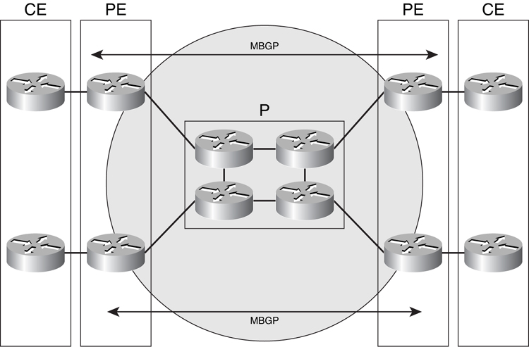
In MPLS-VPN, additional terms are introduced to describe the architecture shown in [Figure 8-31](https://learning.oreilly.com/library/view/building-resilient-ip/1587052156/ch08.html#ch08fig31):
• **Customer edge (CE) router**—The router that the customer used to connect to the service provider
• **Provider edge (PE) router**—The router with which the service provider connects to the customer router
• **Provider (P) router**—The router within the service provider MPLS network that connects to the PE routers
To enable MPLS-VPN, Multiprotocol BGP (MBGP) must be running between all the PE routers. MPLS-VPN uses MBGP to propagate label information on the respective VPN, as illustrated in [Figure 8-32](https://learning.oreilly.com/library/view/building-resilient-ip/1587052156/ch08.html#ch08fig32).
**Figure 8-32** _Single VPN in MPLS-VPN_
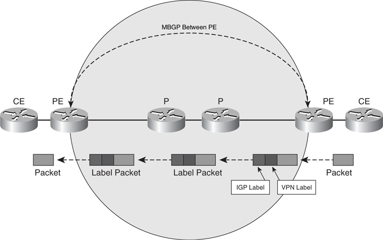
For a single VPN, such as the example shown in [Figure 8-32](https://learning.oreilly.com/library/view/building-resilient-ip/1587052156/ch08.html#ch08fig32), the two PE routers will have the VPN configured, and the MBGP will be used to exchange information on the VPN between the PE routers. In the example, when a packet from the CE router arrives in the PE router, the PE tags it with a VPN label. When the PE sends the packet to a P router, it tags the packet with an additional forwarding label derived from IGP. Therefore, when the packet is sent across the network, it actually contains two labels. When the packet arrives at the destination PE router, the PE router strips the labels and sends the IP packet to the target CE router. The P router does not care about the VPN label; it just forwards the packet based on the label derived from IGP.
Note
This section uses an example of MPLS with a single VPN. Although you can create multiple VPNs, the configuration example is restricted to only one VPN for simplicity.
In [Figure 8-33](https://learning.oreilly.com/library/view/building-resilient-ip/1587052156/ch08.html#ch08fig33), there is a single VPN known as RED VPN with two CE routers involved. The service provider’s MPLS network is built up with only four routers: two P routers and two PE routers.
**Figure 8-33** _MPLS-VPN Example_
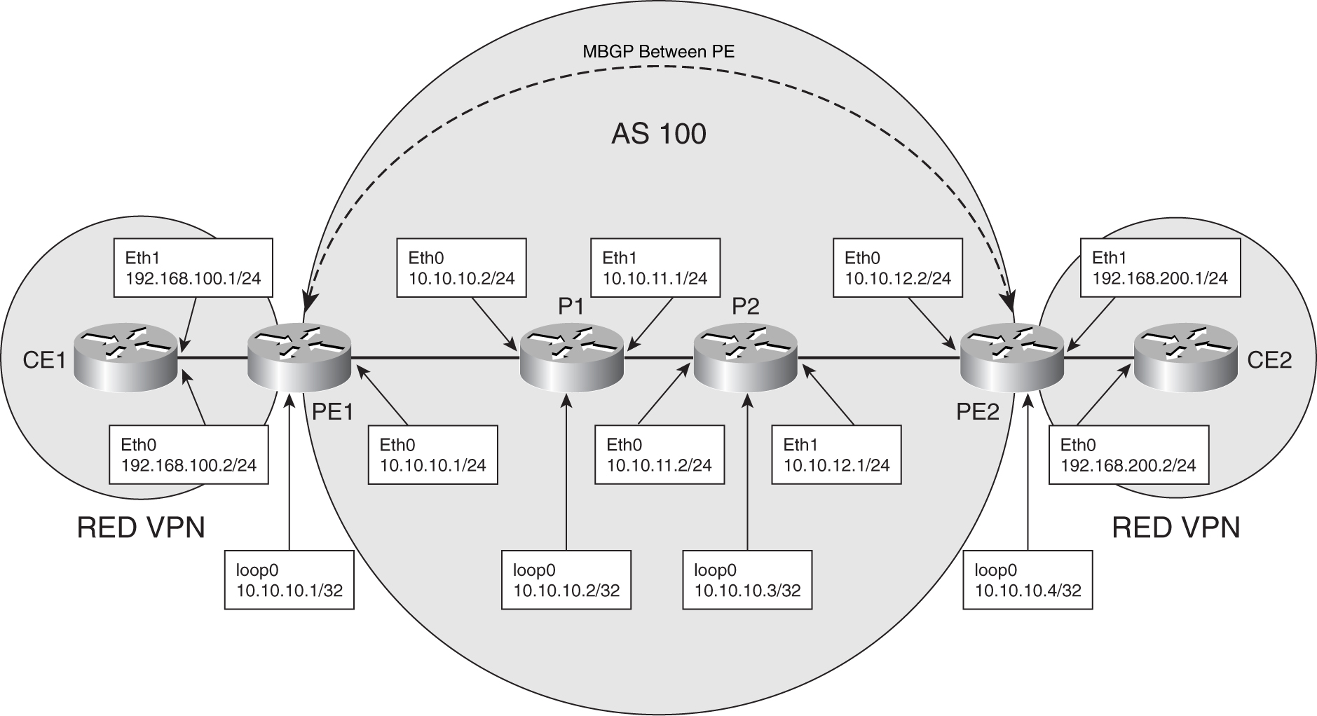
The configuration for the P routers is the simplest and is shown in [Example 8-13](https://learning.oreilly.com/library/view/building-resilient-ip/1587052156/ch08.html#ch08ex13).
**Example 8-13** _Configuration for Both P Routers (P1 and P2)_
---
Router P1
!
! CEF forwarding needs to be enabled
!
ip cef
!
interface loopback0
ip address 10.0.0.2 255.255.255.255
!
interface Ethernet 0
ip address 10.10.10.2 255.255.255.0
tag-switching ip
!
interface Ethernet 1
ip address 10.10.11.1 255.255.255.0
tag-switching ip
!
router ospf 1
network 10.0.0.0 0.0.0.255 area 0
network 10.10.10.0 0.0.0.255 area 0
network 10.10.11.0 0.0.0.255 area 0
Router P2
!
! CEF forwarding needs to be enabled
!
ip cef
!
interface loopback0
ip address 10.0.0.3 255.255.255.255
!
interface Ethernet 0
ip address 10.10.11.2 255.255.255.0
tag-switching ip
!
interface Ethernet 1
ip address 10.10.12.1 255.255.255.0
tag-switching ip
!
router ospf 1
network 10.0.0.0 0.0.0.255 area 0
network 10.10.11.0 0.0.0.255 area 0
network 10.10.12.0 0.0.0.255 area 0
---
The PE router will be more complicated with MBGP running, as shown in [Example 8-14](https://learning.oreilly.com/library/view/building-resilient-ip/1587052156/ch08.html#ch08ex14).
**Example 8-14** _Configuration of Both PE Routers (PE1 and PE2)_
---
Router PE1
!
! CEF forwarding needs to be enabled
!
ip cef
!
! define RED VPN
!
ip vrf RED
rd 100:1
route-target export 100:1000
route-target import 100:1000
!
interface loopback0
ip address 10.0.0.1 255.255.255.255
!
! Ethernet 0 to connect to P router
!
interface Ethernet 0
ip address 10.10.10.1 255.255.255.0
tag-switching ip
!
! Ethernet 1 to connect to CE router
!
interface Ethernet 1
ip vrf forwarding RED
ip address 192.168.100.1 255.255.255.0
!
router ospf 1
network 10.0.0.0 0.0.0.255 area 0
network 10.10.10.0 0.0.0.255 area 0
!
Router bgp 100
!
! establish BGP session with other PE
!
neighbor 10.10.10.4 remote-as 100
neighbor 10.10.10.4 update-source Loopback0
!
address-family vpnv4
neighbor 10.10.10.4 activate
neighbor 10.10.10.4 send-community both
exit-address-family
!
! command for VPN RED
!
address-family ipv4 vrf RED
redistribute connected
exit-address-family
!
Router PE2
!
! CEF forwarding needs to be enabled
!
ip cef
!
! define RED VPN
!
ip vrf RED
rd 100:1
route-target export 100:1000
route-target import 100:1000
!
interface loopback0
ip address 10.0.0.4 255.255.255.255
!
! Ethernet 0 to connect to P router
!
interface Ethernet 0
ip address 10.10.12.2 255.255.255.0
tag-switching ip
!
! Ethernet 1 to connect to CE router
!
interface Ethernet 1
ip vrf forwarding RED
ip address 192.168.200.1 255.255.255.0
!
router ospf 1
network 10.0.0.0 0.0.0.255 area 0
network 10.10.12.0 0.0.0.255 area 0
!
Router bgp 100
!
! establish BGP session with other PE
!
neighbor 10.10.10.1 remote-as 100
neighbor 10.10.10.1 update-source Loopback0
!
address-family vpnv4
neighbor 10.10.10.1 activate
neighbor 10.10.10.1 send-community both
exit-address-family
!
! command for VPN RED
!
address-family ipv4 vrf RED
redistribute connected
exit-address-family
---
The CE router will see only the interface to the respective PE router. It does not have visibility to the MPLS network. Given that the individual CE to PE interface has its own IP subnet, the PE router routes those subnets across using MBGP. Notice that in the PE’s MBGP configuration, there is a statement to **redistribute connected**. The **redistribute connected** command takes the connected routes of the CE and injects the routes into the routing table of the VPN. When the routes are available in the VPN routing table, other CEs within the VPN gain connectivity via those connected routes.
The configuration for the CE routers is simple, with a default route pointing to the respective PE routers, as shown in [Example 8-15](https://learning.oreilly.com/library/view/building-resilient-ip/1587052156/ch08.html#ch08ex15).
**Example 8-15** _Configuration of the CE Routers_
---
Router CE1
!
interface Ethernet 0
ip address 192.168.100.2 255.255.255.0
!
ip route 0.0.0.0 0.0.0.0 192.168.100.1
!
Router CE2
!
interface Ethernet 0
ip address 192.168.200.2 255.255.255.0
!
ip route 0.0.0.0 0.0.0.0 192.168.200.1
---
One key advantage of MPLS-VPN is the ability to create a VPN of multiple sites. [Figure 8-34](https://learning.oreilly.com/library/view/building-resilient-ip/1587052156/ch08.html#ch08fig34) shows a single VPN with four sites connected to a single MPLS-VPN service provider.
**Figure 8-34** _MPLS-VPN with Multiple Sites_
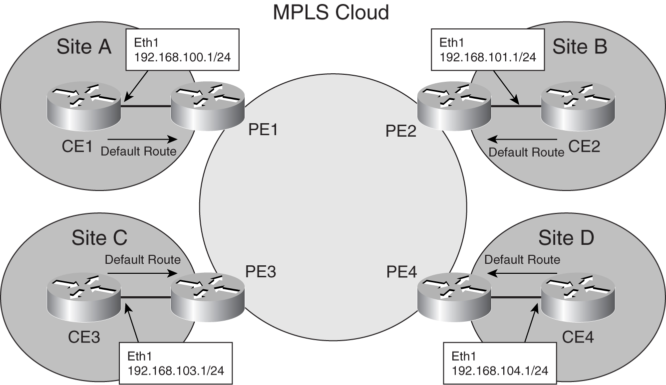
Configuration for the CE router at individual sites could be as simple as a default route to the PE routers, as shown in [Example 8-16](https://learning.oreilly.com/library/view/building-resilient-ip/1587052156/ch08.html#ch08ex16).
**Example 8-16** _Configuration of the CE Router at Site A_
---
Router CE1
!
interface Ethernet 0
ip address 192.168.100.2 255.255.255.0
!
ip route 0.0.0.0 0.0.0.0 192.168.100.1
!
---
With such configuration, the responsibility of routing multiple sites resides with the service provider network, using MBGP to route the traffic across multiple sites.
However, a single default route to the service provider does not offer the ability to have multiple paths to the other sites. You can run a routing protocol such as OSPF between the CE and PE routers to improve resiliency by allowing the CE routers to have multiple paths to each other.
Shown in [Figure 8-35](https://learning.oreilly.com/library/view/building-resilient-ip/1587052156/ch08.html#ch08fig35), a similar example to [Figure 8-34](https://learning.oreilly.com/library/view/building-resilient-ip/1587052156/ch08.html#ch08fig34), CE routers have serial leased lines to each other.
**Figure 8-35** _MPLS-VPN with Multiple Sites Running OSPF with PE_
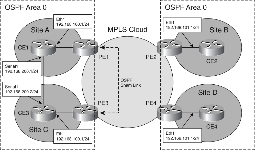
All the CE routers belong to OSPF Area 0. CE routers in Site A and Site C have a serial leased line connected to each other.
The PE routers need to have OSPF configured and running between the link and the PE and the CE, as shown in [Example 8-17](https://learning.oreilly.com/library/view/building-resilient-ip/1587052156/ch08.html#ch08ex17).
**Example 8-17** _Configuration of the PE Routers Running OSPF with CE_
---
Router PE1
!
! define RED VPN
!
ip vrf RED
rd 100:1
route-target export 100:1000
route-target import 100:1000
!
! Configuration for ospf for VPN RED
!
router ospf 10 vrf RED
network 192.168.100.0 0.0.0.255 area 0
area 0 sham-link 192.168.100.2 192.168.103.2 cost 40
!
Router bgp 100
!
! establish BGP session with other PE.
! One set of BGP peering command is shown for brevity
!
neighbor 10.10.10.4 remote-as 100
neighbor 10.10.10.4 update-source Loopback0
!
address-family vpnv4
neighbor 10.10.10.4 activate
neighbor 10.10.10.4 send-community both
exit-address-family
!
! command for VPN RED
!
address-family ipv4 vrf RED
redistribute connected
redistribute ospf 10
exit-address-family
---
Shown in [Example 8-17](https://learning.oreilly.com/library/view/building-resilient-ip/1587052156/ch08.html#ch08ex17), a separate instance of an OSPF process has been created for VRF RED, which is the VPN ID. The command is **router ospf 10 vrf RED**. Within the configuration for MBGP for VRF RED, the additional command **redistribute ospf 10** is configured to allow OSPF routes to be injected into VRF RED.
Referring to [Figure 8-34](https://learning.oreilly.com/library/view/building-resilient-ip/1587052156/ch08.html#ch08fig34), the serial link between CE1 and CE3 becomes a backdoor link for the MPLS-VPN. OSPF treats the link through MPLS-VPN as a interarea route, and the backdoor link as a intra-area route. The intra-area route will be more preferred than the interarea route. To get around the problem, a sham link is created between the PE1 and PE3 router. A _sham link_ is an intra-area link. With a sham link, the path between the MPLS-VPN will be used. As shown in [Example 8-17](https://learning.oreilly.com/library/view/building-resilient-ip/1587052156/ch08.html#ch08ex17), the sham link is configured with the command **area 0 sham-link 192.168.100.2 192.168.103.2 cost 40**, where 192.168.100.2 is the address for PE1, and 192.168.203.2 is the address for PE2. A similar command has to be configured in PE2.
[Example 8-18](https://learning.oreilly.com/library/view/building-resilient-ip/1587052156/ch08.html#ch08ex18) shows the configuration for a CE router running OSPF at Site A.
**Example 8-18** _Configuration of CE Router Running OSPF at Site A_
---
Router CE1
!
interface Ethernet 0
ip address 192.168.100.2 255.255.255.0
!
Interface Serial 0
ip address 192.168.200.1 255.255.255.0
!
router ospf 10
network 192.168.100.0 0.0.0.255 area 0
network 192.168.200.0 0.0.0.255 area 0
!
---
MPLS-VPN enables you to connect multiple sites together with a single VPN. At the same time, using another WAN connectivity such as leased line, you can build a resilient and cost-effective WAN network.
### Summary
This chapter covered various WAN connectivity options to build a resilient IP infrastructure. The choice of WAN connectivity is determined by bandwidth requirements, but unfortunately your choices are often restricted by costs and availability. If you have multiple WAN connectivity working together, you can reduce dependency on a single element and improve resiliency of the overall IP infrastructure.
table of contents
search
Settings
[Chapter 7. Internet Module](https://learning.oreilly.com/library/view/building-resilient-ip/1587052156/ch07.html)
Chapter 8. WAN Module
queue
Building Resilient IP Networks
[Chapter 9. Data Center Module
](https://learning.oreilly.com/library/view/building-resilient-ip/1587052156/ch09.html)