[Skip to Content](https://learning.oreilly.com/library/view/building-resilient-ip/1587052156/ch09.html#main)
[](https://learning.oreilly.com/home/)
- Explore Skills
- Start Learning
- Featured
[Answers](https://learning.oreilly.com/answers2/)
Search for books, courses, events, and more
## Chapter 9. Data Center Module
---
This chapter covers the following topics:
• [Data Center Environmental Considerations](https://learning.oreilly.com/library/view/building-resilient-ip/1587052156/ch09.html#ch09sec1lev1)
• [Data Center Network Considerations](https://learning.oreilly.com/library/view/building-resilient-ip/1587052156/ch09.html#ch09sec1lev2)
• [Data Center Network Architecture](https://learning.oreilly.com/library/view/building-resilient-ip/1587052156/ch09.html#ch09sec1lev3)
• [Data Center Network Security](https://learning.oreilly.com/library/view/building-resilient-ip/1587052156/ch09.html#ch09sec1lev4)
• [Service Optimization](https://learning.oreilly.com/library/view/building-resilient-ip/1587052156/ch09.html#ch09sec1lev5)
• [Integrated Service Modules](https://learning.oreilly.com/library/view/building-resilient-ip/1587052156/ch09.html#ch09sec1lev6)
---
Information is, perhaps, the most important asset that a company possesses. With almost all companies storing their information in digital form, data centers are becoming the most important physical asset a company has. The importance of data centers in the entire IT asset can never be underestimated. After all, the aim of the whole IT infrastructure is to transport and process information. Without information, there is not much use for the IT infrastructure. Therefore, the discussion of a resilient IP network has to include a resilient data center module.
Unlike yesteryear when data centers could just mean a room that housed some servers, the construction of a modern data center is a technical task. The power requirement, the air conditioning, and even cabling require professional and technical know-how.
As for the networking aspect, a data center module is not as straightforward as it seems. It is more than merely connecting a bunch of servers to a network. One important point to note is how the physical aspects of a data center and its network design influence each other. Each is closely related and dependent on the other. Therefore, various factors must be considered when dealing with data center resiliency. The environmental aspects of the data center include the following:
• The amount of real estate available within the data center affects rack layout.
• The amount of power and air conditioning available affects what kind of equipment that can be deployed.
• The cabling layout, if not done properly from day one, can mean a disastrous mess when expansion takes place.
Other than the environmental aspects, changes in the way people access information, and the proliferation of hacking and denial-of-service (DoS) attacks on the Internet, affect how networks are constructed within the data center. With the introduction of new Layer 2 and Layer 3 networking technology to tackle these changes, today’s data center networks differ from those of the past. Technologies that address information availability and scalability have emerged in recent years. These technologies, such as content networking, have contributed to the totally new idea of making information available around the clock.
As part of the discussion on constructing the data center module, this chapter touches on some of these factors and highlights some new features that have been successfully deployed.
### Data Center Environmental Considerations
This section considers how network design is influenced by environmental factors within the data center and vice versa. Not many of us have the luxury of being involved in the planning and construction of a new data center. Many of us step into an already existing data center. Therefore, you must work within the constraints of the existing data center—lack of space, a cooling problem, and so on. The following sections cover various physical aspects of data centers and discuss how they contribute to the resiliency of a data center module.
#### Cabling
Cabling is definitely the most “unglamorous” part when it comes to data center discussion. Often, cabling is treated as an afterthought, with jobs being done by technicians. The fact is, cabling and network design are intertwined, and it is as technical a subject as networking design can be.
A well-designed cabling plant improves operational efficiency and helps in maintaining network resiliency. It is common to walk into a data center and see cables dangling from the ceiling or snaking across the floors. These scenarios are perfect to produce a network problem. In the worst-case scenario, precious time is wasted in troubleshooting when a network manager has to sort through a cable mess to figure out which cable goes to which switch port.
This section describes important components of proper cabling:
• [Tagging](https://learning.oreilly.com/library/view/building-resilient-ip/1587052156/ch09.html#ch09sec3lev1)
• [Documentation](https://learning.oreilly.com/library/view/building-resilient-ip/1587052156/ch09.html#ch09sec3lev2)
• [Discipline](https://learning.oreilly.com/library/view/building-resilient-ip/1587052156/ch09.html#ch09sec3lev3)
##### Tagging
Network managers often fail to tag cables. A tagged cable on both ends helps with easy location of the connected devices. When a high-profile network breaks down, every minute counts when trying to bring the network service back up. In this type of scenario, the pressure on network managers can be great. The last thing that you want is to do cable tracing under duress. A well thought out tagging system helps to eliminate this chore and improves confidence and assurance under difficult situations. The use of different color cables and tags for different devices is an extremely helpful method. A proper cabling system from the beginning minimizes the likelihood of cable faults and aids in reducing troubleshooting time, leading to a higher availability number for the network.
##### Documentation
Another area that is closely related to tagging but that is mostly ignored is documentation. Besides having diagrams showing the logical network designs, it is important to have documentation of the physical connectivity, too. A detailed diagram showing which port of a router is connected to which port of a switch is extremely important, especially when it comes to remote troubleshooting of a network. Such documentation proves crucial when you are trying to ascertain the connectivity status of a particular link. It would be a disaster thinking both sides of a link are up when in actuality you are looking at the status of the wrong port. Again, this is about improving confidence and assurance during troubleshooting time.
##### Discipline
One word sums up the expectation when it comes to cabling: _discipline_. It is common to see a neat and tidy data center on day one, only to turn into a mess of cables within six months. This happens as new devices are added and new cables are added haphazardly, crisscrossing from rack to rack. Many network managers think tagging can wait and documentation can be followed up, but procrastination and lack of discipline are the enemies of data center operation. Therefore, strict operational procedure has to be enforced. One good policy to follow is to have regular monthly or yearly “cleanup” exercises for the data center so that a proper operating environment can be maintained.
All works that are carried out within the data center, even just the laying of a single cable, must be planned. Preparation work has to be done well before the actual work. Such preparation includes the approval, switch port assignment, proper cable run, patch panel assignment, tagging, documentation, and a scheduled time slot. All these things should be done even before the new device is brought into the data center. In reality, it is the reverse that happens. Somebody brings a new device in, powers it up, looks for a cable that is lying on the floor, runs it in the “shortest path” manner, and plugs it into a convenient switch port. For this type of operation, there is no point talking about network resiliency.
#### Rack Space
Many network managers may realize that a data center is about dealing with real estate. Just as real estate in a downtown area is expensive, the rack space within a data center is precious.
The importance of planning for space in the data center cannot be ignored. Proper planning for rack space means networking equipment can be located conveniently and correctly within the data center, which not only helps in operational efficiency but also ultimately contributes to network resiliency. Rack-space planning is important, especially if the data center experiences frequent change. For example, if no space allowance is provided, replacing a smaller switch with a bigger one might prove impossible, or worse, other devices might have to be remounted to make way for a new device. In such a case, moving equipment means a longer downtime.
#### Server Size
Server technology has undergone tremendous changes over the past few years. Two areas profoundly impact the data center network design: the physical size and performance of the server.
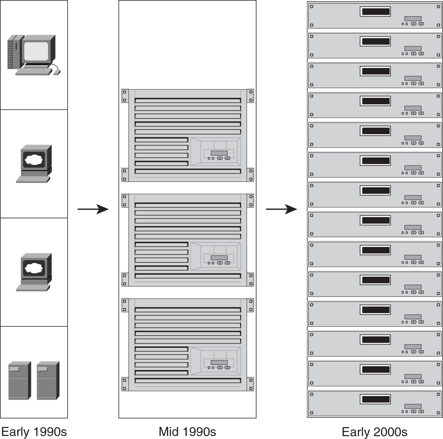
As shown in [Figure 9-1](https://learning.oreilly.com/library/view/building-resilient-ip/1587052156/ch09.html#ch09fig01), except for those top-end high-performance servers, most servers have experienced some downsizing in recent years. The physical dimensions of servers are getting smaller, and yet they pack the same, if not more, compute power than their predecessors. The proliferation of 1-RU servers, or rack-mount servers, has changed the look of the data center and affects how data center networks are designed.
**Figure 9-1** _Changes in the Server Size_
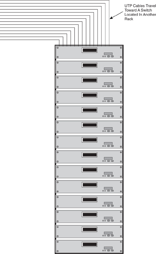
There are two ways to connect these 1-RU servers physically to the network. The first is to have these servers connected via unshielded twisted-pair (UTP) cables to a switch that is located in another rack, as shown in [Figure 9-2](https://learning.oreilly.com/library/view/building-resilient-ip/1587052156/ch09.html#ch09fig02). For a small number of servers, this is still manageable, especially for the rack that contains the switch. However, when many racks of servers need to be connected in this manner, cabling can become quite an issue. Imagine the load on the cable tray leading to the rack containing the switch. In addition, jamming hundreds of cables into a single rack can be a problem, to say the least.
**Figure 9-2** _Running UTP Cables to an External Switch_
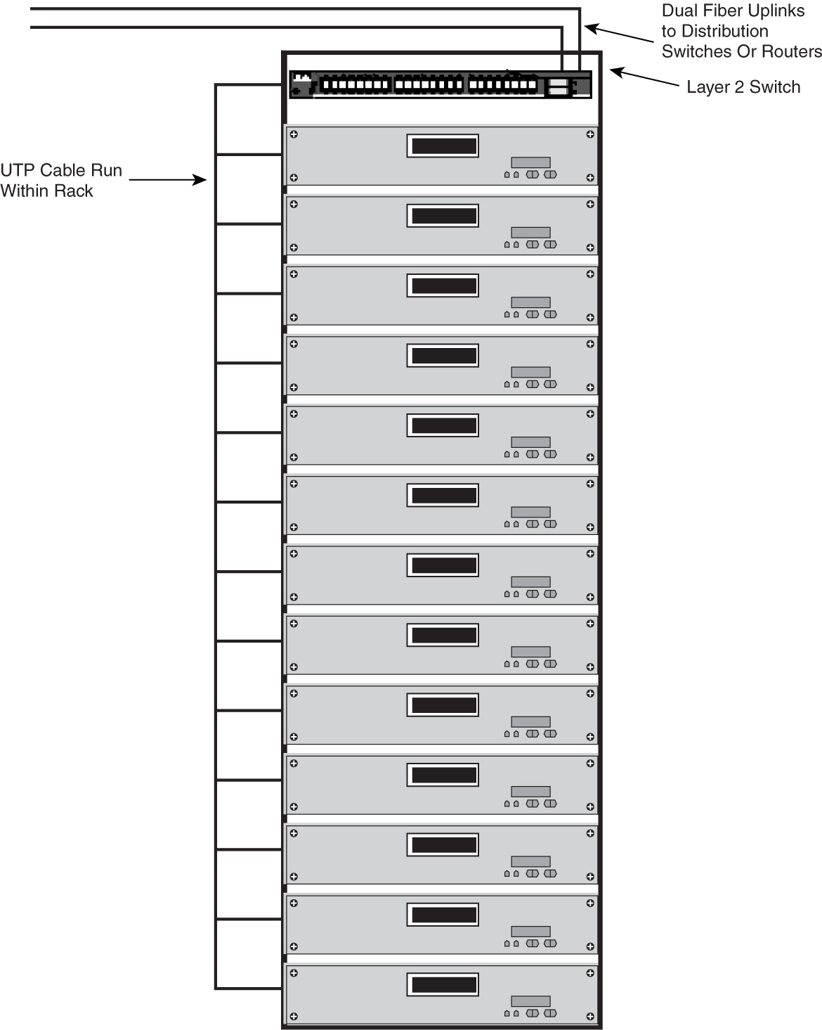
[Figure 9-3](https://learning.oreilly.com/library/view/building-resilient-ip/1587052156/ch09.html#ch09fig03) shows another way to connect the servers to the network. In this option, all the servers are connected to a small switch within the same rack. This small form-factor switch, typically 1-RU in size, can be both Layer 2 or Layer 3, depending on the logical network design. In this case, what comes out of the server rack is just a pair of fiber that connects the small switch to its upstream connection. The upstream connections can typically be a pair of distribution switches or a pair of routers. The benefit of this option is neater cabling running within the data center. All the UTP cables, which are bulky and harder to manage, are confined within the rack. The problem with this option is the cost associated with the introduction of those 1-RU switches within the server rack. In the case of a distribution switch as upstream, it also means the introduction of the Spanning Tree Protocol (STP) between the racks. The STP introduces another factor that determines the resiliency of the server resources. From a network management perspective, this also means more devices to monitor and manage. From an inventory perspective, this might mean more parts to stock for spares, which ultimately adds to the cost. Another limitation of this design is that servers must be connected to a different switch to satisfy some requirements.
**Figure 9-3** _Alternative Cabling Option_
Note that physical connectivity does not affect the Layer 3 design of the data center. Therefore, it is possible to see a mix of these two options within the same data center. The point to note is that each method has its pros and cons, and it is difficult to say which is better than the other. The decision will often depend on the operational requirements, preferences, and the network manager’s familiarity with a particular setup.
#### Power
Power is one important consideration when it comes to data center readiness. It is important to note how the new generation of networking equipment and new technologies affect the sizing of the power requirement within the data center.
Consider network speed, for example. Just a few years ago, a 100-Mbps backbone was considered high speed. Today, even a gigabit backbone pales in comparison with those that deploy a 10-Gbps network. In fact, some networks have a 40-Gbps link capacity. As network speed gets faster and faster, it is important to know that the power to drive this kind of speed is increasing, too. A power-supply module of a network device that was purchased three years ago might not be enough to drive the high-speed modules of today. Likewise, the power supply within the data center might not be adequate to drive a new network infrastructure of today.
A good example is the Cisco Catalyst 6513 switch. With a total of 13 slots, it needs a lot of power to drive those modules within the slots. The power supply for the Catalyst 6500 used to be 1000 watts (W). Today, the power-supply module of the Catalyst 6513 measures 6000 W, with an input current of 20 amps. Not many data centers can provide a 20-amp input.
Another good example is the Cisco Carrier Routing System, the CRS-1. With a power rating of 16.56 kW, it certainly needs some major power upgrading and site preparation before installation.
Another area of development that affects the power-supply requirement within a data center is IP telephony. With the introduction of IP phones, the switch not only has to provide data connectivity but also power to drive the phone. The power supply for a Catalyst switch used to be just for the modules alone. But today, more power is required to drive the IP phones attached to the switch. Imagine installing a Catalyst 6513 with the 48-port 10/100 Ethernet modules. Each of the 10/100 Ethernet ports has an IP phone attached to it. You would have to plan carefully for the power required.
Not only do you need to look into the primary power requirement, you also have to revise the standby power. For example, with a load of 6000 W power module, you must review your uninterruptible power supply (UPS). By the time a power failure occurs, it is too late to realize that you have an inadequate UPS. In addition, if you are deploying a power generator, you must make sure that you have stored enough fuel for emergency purposes. If you neglect to assess both primary and standby power needs, you compromise data center resiliency.
#### Next-Generation Server Architecture
In the server arena, one of the most significant developments is the introduction of the blade server products. These new products from vendors such as IBM, HP, and Dell literally change the way servers are deployed within the data center.
The blade servers are slim in size, and they slide into a common chassis, sharing power supply, fan, floppy drive, and switch ports. With their own processor, memory, and operating systems, each is an independent server. With a single chassis supporting up to 14 servers, these machines pack high-density computing power. One benefit of a blade server is that cabling becomes neater. They also come with their own mini network within their chassis. However, connecting these mini networks is something new that the network manager faces.
As shown in [Figure 9-4](https://learning.oreilly.com/library/view/building-resilient-ip/1587052156/ch09.html#ch09fig04), blade servers typically come with a dual network interface card (NIC) configuration for redundancy purposes. These NICs are connected to the backplane of the chassis, where there may be modules that aggregate these connections and provide connectivity to the outside world. These modules, sometimes called the _pass-through modules_, provide for both copper and fiber connections through special cable. Depending on the speed and distance requirements, the connections are typically 100- or 1000-Mbps Ethernet.
**Figure 9-4** _Blade Server Connectivity_
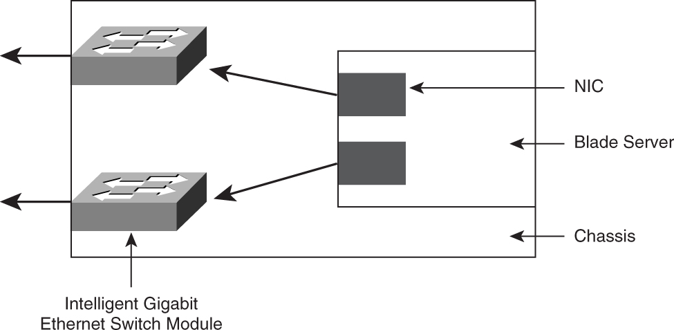
Another way to provide network connectivity to these servers is to have a mini switch, which comes in the form of a module that resides in the chassis. One example of this module is the Cisco Intelligent Gigabit Ethernet Switch Module (IGESM). It plugs into the IBM eServer Bladecenter chassis and is based on the Cisco Catalyst 2950 image. The connections out of the IGESMs are two trunk ports that connect to a pair of distribution switches. In this case, STP plays an important role in providing a loop-free Layer 2 network.
Blade servers have certainly changed the way servers are connected to the network. They introduce new challenges in areas such as power requirements, floor space loading, and cooling. In the area of network connectivity, the obvious challenge is to ensure that both Layer 2 and Layer 3 resiliency continue to work. Fortunately, products such as the IGESM ensure that feature interoperability is not an issue (because IGESM is based on the same Catalyst family of code).
So far, you have learned about only the physical aspects of data centers. Through extensive deployment experience and proper planning, the physical aspects tend to become easier to deal with than other areas, such as information security and network design. If you want to learn more about the construction of a data center, refer to _Build the Best Data Center Facility for Your Business_, by Douglas Alger (Cisco Press, 2005).
Besides the physical aspects, you must consider other factors when designing a data center network, as discussed in the following section.
### Data Center Network Considerations
Designing a data center network differs from designing a normal campus-access network. It is more than just connecting a group of servers to a network. Some design considerations within a data center network are not found in other parts of a network. Besides those environmental considerations mentioned in the previous section, various important factors, such as security, server performance, fault tolerance, and multifaceted servers, need to be considered. These factors determine design philosophy and the choice of features, and ultimately influence the selection of equipment to be deployed within the data center.
#### Security
With important assets such as servers and databases residing within the data center, it is the center of focus for all hackers. To develop a data center network architecture that can mitigate cyber attacks, security has to be part of the network architecture from day one. It is tempting, and as a result disastrous, to treat security as an afterthought when developing a data center network. Unfortunately, many network managers ignore this advice, and they pay the hefty price of being compromised.
With the focus on securing the information infrastructure, many security features have been developed in the routing and switching products from Cisco Systems. Some of these technologies are applied solely in data center environments. These features help network managers to defend against threats and attacks. However, their use has to be factored into the architecture from day one, because ad hoc or incremental introduction might prove difficult to manage. Or worse, it might result in problems such as nonoptimized routing within the data center network. The new features are discussed in the section “[Data Center Network Security](https://learning.oreilly.com/library/view/building-resilient-ip/1587052156/ch09.html#ch09sec1lev4).”
Also, a good source of information for a security architecture is the Cisco Security Blueprint for Enterprise Networks (SAFE). It includes best practices and design recommendations for implementing security in various parts of the network. You can find more information about SAFE at the following URL:
[http://www.cisco.com/go/safe](http://www.cisco.com/go/safe)
#### Server Performance
Server performance profoundly impacts the way data center networks are designed. In normal campus-access networks, users spend most of their time on activities such as typing and reading. During this time, the network connection is actually idling. For example, think about a 48-port access switch that connects to a group of users. Even though these users share a common 1-Gbps uplink, plenty of network bandwidth is available to serve this group of users.
Servers, however, behave differently than the end stations. Because servers are supposed to serve hundreds, if not thousands, of user connections at any given time, they are kept busy almost all the time. In addition, with the introduction of high-performance network interface cards, the new-generation servers are fully capable of generating gigabits of traffic at the line rate. If each server within a rack generates a line rate of traffic most of the time, the network architecture has to be able to address this traffic load and at the same time provide features and redundancy required to make sure information is available around the clock. Sizing of the uplink bandwidth and choice of equipment now takes on a new dimension.
The performance of these new servers affects how they should be connected to the network. For example, aggregating many high-performance servers to a single low-end access switch, typically with 1- or 2-Gb connections, may pose a serious performance issue. This issue, together with that discussed in the section “[Server Size](https://learning.oreilly.com/library/view/building-resilient-ip/1587052156/ch09.html#ch09sec2lev3),” illustrates the complexity of data center design.
#### Fault-Tolerant Server Features
To increase server network availability, various NIC and server vendors have developed different technologies to address this issue. The following are some of the well-known technologies:
• Cisco Fast EtherChannel (FEC)
• Cisco Gigabit EtherChannel (GEC)
• HP trunking
• HP Network Fault Tolerance (NFT)
• HP Transmit Load Balancing (TLB)
• Linux Bonding Active Backup
• Linux Bonding Round Robin
• Linux Bonding XOR
• Sun Trunking
• Microsoft Network Load Balancing (NLB)
• IBM High-Availability Cluster Multiprocessing (HACMP)
Each of these technologies works differently to achieve the same goal: to prevent a single point of failure for accessibility to the server. Although some merely provide redundancy at network connectivity level, others provide for full server redundancy. Some work at the Layer 2 level by working around the Media Access Control (MAC) address, whereas some work at the Layer 3 level on the IP address. Which of these technologies you choose to deploy will ultimately affect how the design of your logical IP network performs. Obviously, it also determines how the physical connectivity has to be carried out.
#### Multifaceted Server
For performance and security reasons, the data center architecture has to take on the concept of multifaceted servers. That is, servers have multiple network interfaces to serve different functions:
• A public-facing interface for serving the information to all users
• A private-facing interface for management purposes
• A backup interface for backing up vital information
The network needs to be constructed to cater to these needs. Issues that you must address include how to separate these interfaces at the Layer 3 level and how to provide physical connectivity for these interfaces. Dealing with these problems may seem straightforward when you have only a few servers; when you have hundreds or thousands of servers, however, this can be a challenging problem. In the section “[Server Size](https://learning.oreilly.com/library/view/building-resilient-ip/1587052156/ch09.html#ch09sec2lev3),” you learned about the problem of having to jam hundreds of cables into a rack. That was for one interface per server. Multiply the problem by three, and you will run into a scalability issue. Obviously, scalability is one important consideration when implementing a solution for servers because of the numbers involved.
### Data Center Network Architecture
So far, you have learned about the various factors that are particular to the data center environment. By now, you should realize that designing a data center network is not as easy as it seems. To incorporate all these considerations into the architecture, you might deploy a unique design philosophy or features that are only applicable to a data center environment.
Although designing the data center module is a complex task, the basics of networking still apply. One important rule still holds true even in the data center module: modularity. Modularity helps you tackle the challenge by dividing the data center network into many subareas. This way, the complex problem can be broken down into manageable blocks that are easy to understand. [Figure 9-5](https://learning.oreilly.com/library/view/building-resilient-ip/1587052156/ch09.html#ch09fig05) shows the high-level building blocks of a data center network.
**Figure 9-5** _Modular Approach to a Data Center Module_
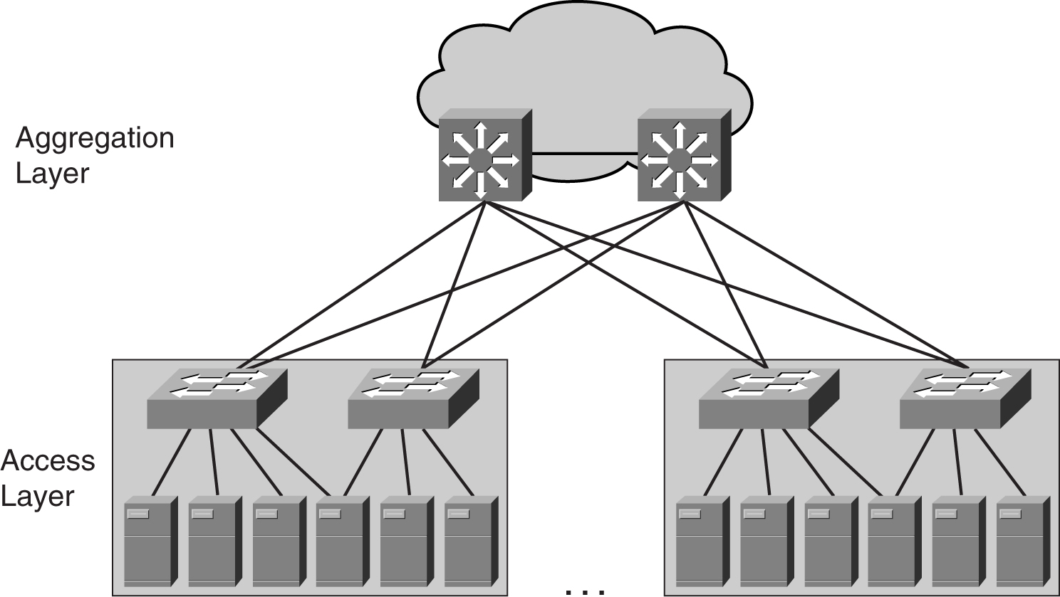
As shown in [Figure 9-5](https://learning.oreilly.com/library/view/building-resilient-ip/1587052156/ch09.html#ch09fig05), there are two portions to the data center module: the access and the aggregation layers. Both of these layers perform different functions, and they are described in the following sections.
#### Access Layer Design
The access layer is the point where the servers are connected to the network. Depending on the network design, the access layer may provide Layer 2 switching only or both Layer 2 and Layer 3 switching functions. In the following discussion, the phrase _server farm_ may mean a single access layer block or it may mean many blocks. In general, a server farm means a group of servers under the same administrative domain. Therefore, there can be many server farms in a data center module.
From an IP network point of view, a server farm is a straightforward design. Just provide an IP subnet, assign IP addresses to the servers, and provide a default gateway function. However, the Layer 2 design may vary, depending on various factors.
For example, the number of servers may dictate how the Layer 2 should be designed. With a few servers, you can connect them to a switch and get the job done. There will be just a few cables to connect, and they will be neatly tucked within a rack. However, when you have tens or hundreds of servers to connect, real estate becomes an issue. Here, real estate points to both the number of switch ports available on a switch and the space to aggregate all the cables. The largest switch today, the Catalyst 6513, can provide 528 10/100/1000-Mbps switch ports (after reserving two slots for the supervisors). Even if you decide to connect that many servers to a single switch, dragging more than 500 UTP cables into a rack is no easy task. In addition, connecting that many servers to a single switch is unwise, because a single switch failure means a massive server outage.
When dealing with access layer design, there are two important influencing factors:
• The physical aspects of the servers, such as size and number
• The logical IP design
When trying to design the access layer, many network managers adopt one of the two design options, or some variation of both.
The first is to provide Layer 2 switching within a single rack. Such a setup is often deployed when there are many 1-RU servers within the rack. Depending on how many interfaces each server has, there can be one, two, or even three 1-RU switches within the rack to provide connectivity, as illustrated in [Figure 9-6](https://learning.oreilly.com/library/view/building-resilient-ip/1587052156/ch09.html#ch09fig06).
**Figure 9-6** _Connectivity Within a Rack_
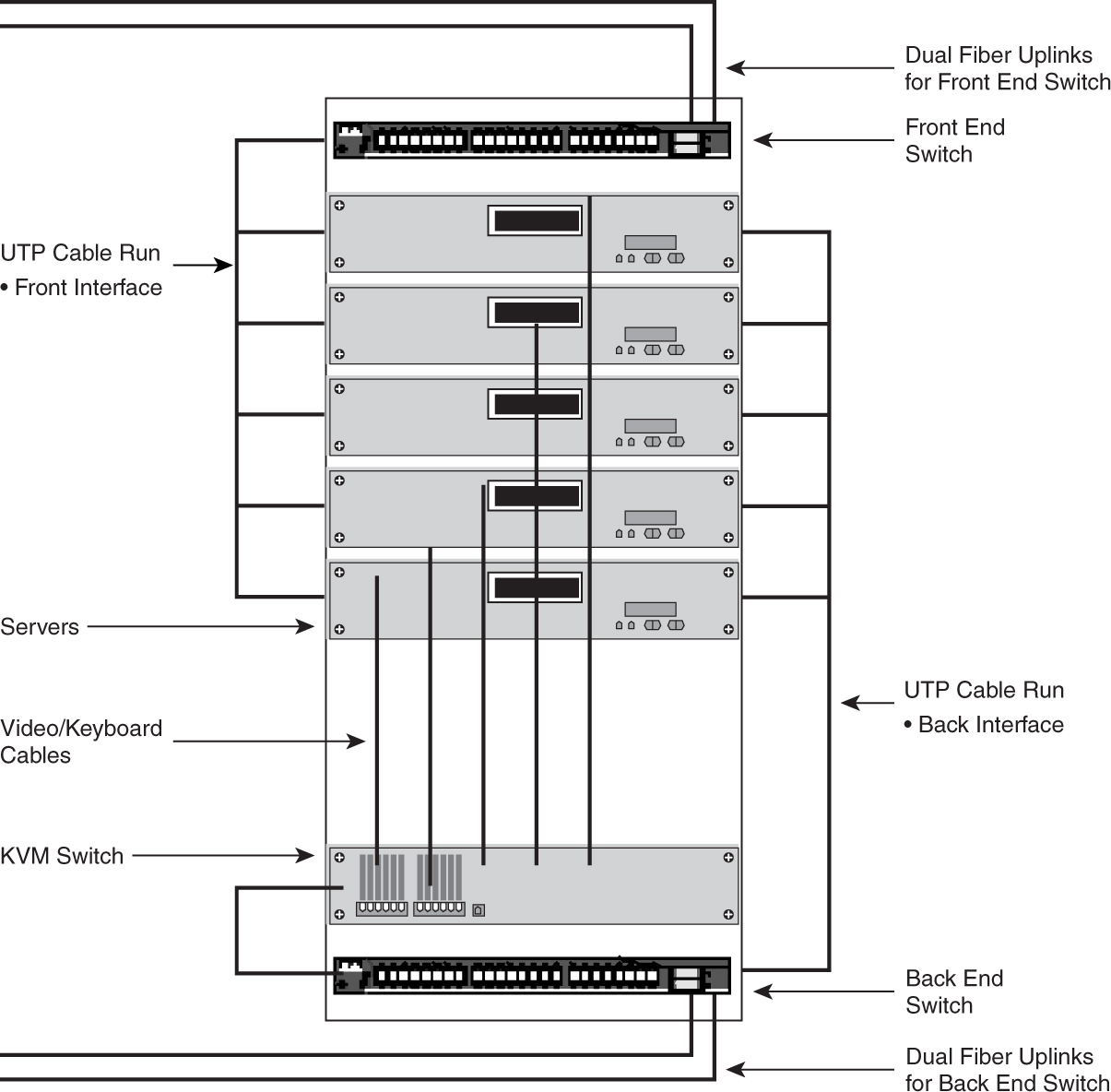
As shown in [Figure 9-6](https://learning.oreilly.com/library/view/building-resilient-ip/1587052156/ch09.html#ch09fig06), besides the servers and the switches, additional equipment may reside within the rack. A good example is a Keyboard-Video-Mouse (KVM) switch, which provides for remote control of the servers, or even an out-of-band network that provides management of the switches.
Advantages of this model include the following:
• The UTP cables are confined within the rack, which makes them easier to manage.
• There will be only a few cables leaving the rack. These are the cables that provide the uplinks from the switches within the rack to the aggregating devices, which are residing in other racks. These cables may still be UTP, or they may be fiber cables.
• The server farm scales by these self-contained racks. This type of scaling enables network managers to partition the server farm into blocks for easier management.
However, critics dislike the model for the following reasons:
• For a really large server farm, there will be too many 1-RU Layer 2 switches in the network. As in all Layer 2 networks, STP plays an important role. Having a large STP domain with too many devices may not be a good idea for a server farm. Introduction of STP also increases the complexity within the server farm.
• Extra cost is incurred in the procurement of those 1-RU switches within the rack.
The second way of connecting the server is to designate a rack to house modular switches to provide for connectivity for all servers, as illustrated in [Figure 9-7](https://learning.oreilly.com/library/view/building-resilient-ip/1587052156/ch09.html#ch09fig07).
**Figure 9-7** _Connecting Servers to a Modular Access Switch_
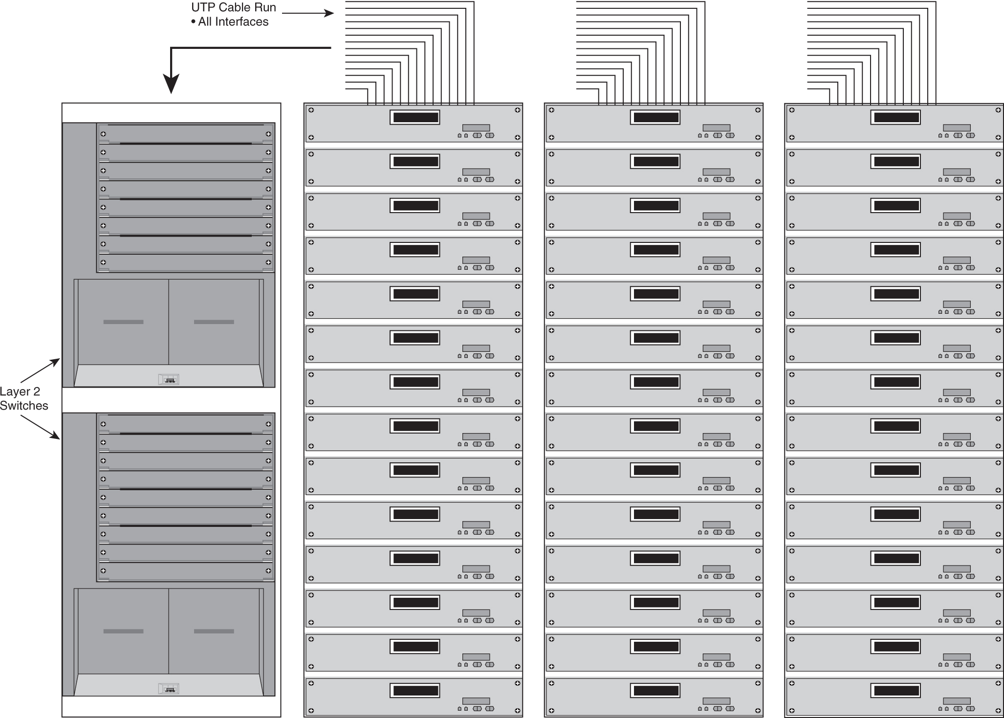
In this model, there are only servers within the rack, and perhaps the KVM switch. All the UTP cables that leave the rack are bound for the Layer 2 switches. Typically, the first rack of the row houses the switch. Therefore, all cables run toward this rack. Some network managers might prefer to place this rack in the middle of the row and thereby shorten the average length of the cable. [Figure 9-8](https://learning.oreilly.com/library/view/building-resilient-ip/1587052156/ch09.html#ch09fig08) shows these two options.
**Figure 9-8** _Possible Locations of Access Switches_
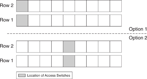
The solution proposed by the second option manages to solve some issues but introduces some cabling challenges to other network managers. This just shows that there will never be a right or wrong access layer design. Both options have their merits, and, in fact, it is very common to see data centers deploying both options. Besides the physical aspect of connectivity, the logical Layer 2 design is an important area of focus.
##### NIC Teaming
One of the most important influencing factors is the fault-tolerant features of the servers, as mentioned in the section “[Server Performance](https://learning.oreilly.com/library/view/building-resilient-ip/1587052156/ch09.html#ch09sec2lev7).” Although features such as the FEC and GEC provide link redundancy, their main aim is to increase overall throughput of the server. The real fault-tolerant feature, in terms of availability of information, is to have more than one network interface working together. This concept, known as NIC teaming, is shown in [Figure 9-9](https://learning.oreilly.com/library/view/building-resilient-ip/1587052156/ch09.html#ch09fig09).
**Figure 9-9** _NIC Teaming_
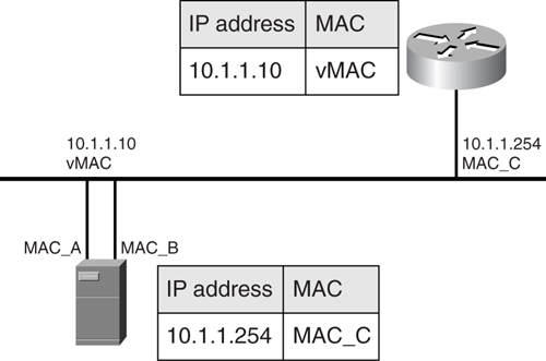
The device driver of the NICs presents a virtual MAC (vMAC) address to the Layer 2 world outside of a single virtual interface. Other devices on the same network map this vMAC address to the actual IP address of the server. This way, when the primary interface fails on the server, the secondary interface takes over. With the vMAC, the rest of the devices on the same network do not have to flush their ARP tables (which means that you can maintain continuous connections).
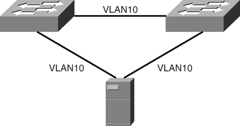
[Figure 9-10](https://learning.oreilly.com/library/view/building-resilient-ip/1587052156/ch09.html#ch09fig10) shows one way to achieve high availability with NIC teaming. With this design, the infrastructure is protected from a single point of failure in the area of connectivity, such as in the server NICs and switch. Note, however, the requirement for the server’s VLAN to span across the switches.
**Figure 9-10** _Possible Physical Connection for NIC Teaming_
In the case of multiple-server VLANs with the same NIC teaming strategy, the STP domains can get quite complex. One good example is when the aggregation layer is introduced, as shown in [Figure 9-11](https://learning.oreilly.com/library/view/building-resilient-ip/1587052156/ch09.html#ch09fig11).
**Figure 9-11** _Redundancy with NIC Teaming_
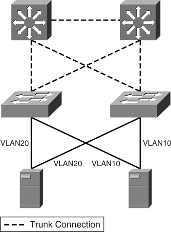
One advantage of having multiple-server VLANs is that you can limit the extent of an outage. A problem in one VLAN will not affect the rest. However, with the server VLANs spanning multiple switches, management of STP of individual VLANs becomes complicated. In this case, you might be tempted to introduce additional features such as MSTP or 802.1s. Remember, however, that introducing more features means introducing complexity (leading to troubleshooting difficulties when errors occur). Spending too much time troubleshooting a server farm VLAN issue means incurring longer downtime when problems occur.
##### Clustering
NIC teaming may mitigate a NIC failure scenario. However, to take the actual server failure into consideration, another technique, called _clustering_, may be introduced. Whereas NIC teaming works at the Layer 2 level, clustering works at Layer 3.
Clustering is a popular way to increase the availability of the server resource. Operating systems from Sun Microsystems, Microsoft, Novell, and Linux provide server clustering solutions. Although they work differently in detail, clustering solutions share the same concept. [Figure 9-12](https://learning.oreilly.com/library/view/building-resilient-ip/1587052156/ch09.html#ch09fig12) shows a typical clustering solution. Basically, more than one server works together, and they present to the rest of the world a single virtual server with an IP address. To keep track of each other’s status, the servers are connected to each other via a private network, and deploy a _heartbeat mechanism_. The use of the heartbeat mechanism is to make sure that their partner is still functioning. The private network is a Layer 2 network.
**Figure 9-12** _Server Clustering_
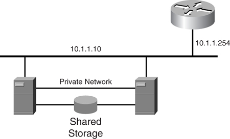
Clustering greatly improves the server farm availability by providing node-level redundancy. The significance of clustering technology is that the network design needs to step up to match the resiliency.
#### Aggregation Layer Design
The aggregation layer within the data center is where the server VLANs are terminated and where the Layer 3 edge begins. The function of the aggregation layer within the data center is similar to that of the distribution module discussed in the section “[Distribution Layer](https://learning.oreilly.com/library/view/building-resilient-ip/1587052156/ch06.html#ch06sec2lev2)” in [Chapter 6](https://learning.oreilly.com/library/view/building-resilient-ip/1587052156/ch06.html#ch06), “[Access Module](https://learning.oreilly.com/library/view/building-resilient-ip/1587052156/ch06.html#ch06).”
As mentioned, the logical IP network of the server farm is straightforward. You need a pair of Layer 3 devices to provide a redundant default gateway service to a group of servers. However, you already saw in the previous sections that the physical connections can vary, even though they achieve the same logical design. The aggregation layer can provide Layer 3 services to the servers in two ways :
• [Trunk ports on an aggregation switch](https://learning.oreilly.com/library/view/building-resilient-ip/1587052156/ch09.html#ch09sec3lev6)
• [Routed ports on an aggregation switch](https://learning.oreilly.com/library/view/building-resilient-ip/1587052156/ch09.html#ch09sec3lev7)
##### Trunk Ports on an Aggregation Switch
[Figure 9-13](https://learning.oreilly.com/library/view/building-resilient-ip/1587052156/ch09.html#ch09fig13) shows one way to connect the server farm access layer to the aggregation layer. The links between the two layers are Layer 2 connections. The ports at both ends of the uplinks are configured as trunk ports. STP is enabled on all switches to ensure a loop-free Layer 2 topology, while the trunk ports carry all VLAN traffic.
**Figure 9-13** _Trunking Between the Access and Aggregation Layers_
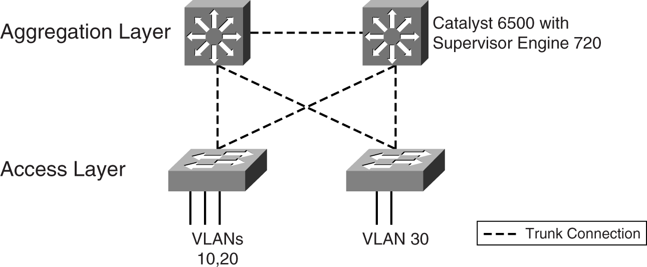
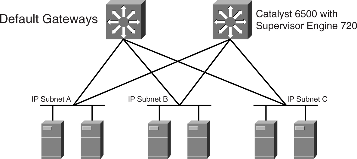
[Figure 9-13](https://learning.oreilly.com/library/view/building-resilient-ip/1587052156/ch09.html#ch09fig13) shows the Catalyst 6500 with the Supervisor Engine 720 to be positioned at the aggregation layer. The supervisor engines in the two aggregation switches provide the Layer 3 function, and are acting as the redundant default gateways for the servers. [Figure 9-14](https://learning.oreilly.com/library/view/building-resilient-ip/1587052156/ch09.html#ch09fig14) shows the resulting Layer 3 network.
**Figure 9-14** _Logical IP Network of a Server Farm_
One characteristic of this design is its capability to support a VLAN that spans multiple access switches while preserving the IP logical design. However, note that spanning a VLAN across access switches is not a recommended design unless it is absolutely necessary. An example of when this can be tolerated is when a pair of fault-tolerant servers that use Layer 2 for a heartbeat needs to be on the same VLAN.
##### Routed Ports on an Aggregation Switch
[Figure 9-15](https://learning.oreilly.com/library/view/building-resilient-ip/1587052156/ch09.html#ch09fig15) shows another way to connect the access layer to the aggregation layer. In this design, the port on the aggregating layer facing the access layer is configured as a routing port. In other words, no STP runs between the ports at the end of the uplinks. The port at the access layer switch is configured as an access port. Even though the Layer 2 design of this option is different from that of [Figure 9-13](https://learning.oreilly.com/library/view/building-resilient-ip/1587052156/ch09.html#ch09fig13), the resulting logical IP network remains the same.
**Figure 9-15** _Routed Ports Between the Access and Aggregation Layers_
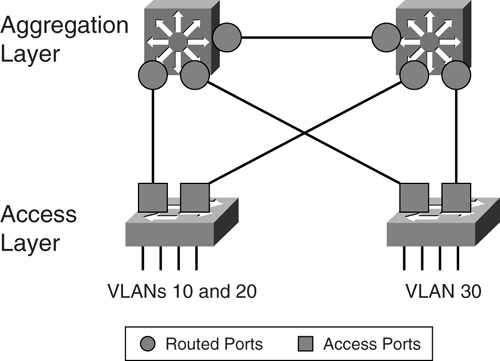
One advantage of this design is its simplicity. Because the STP is confined within the access layer, the aggregating layer runs pure routing protocols only. Even the interconnect between the two aggregating devices is a routed link. The result is a simpler configuration at the aggregating layer devices.
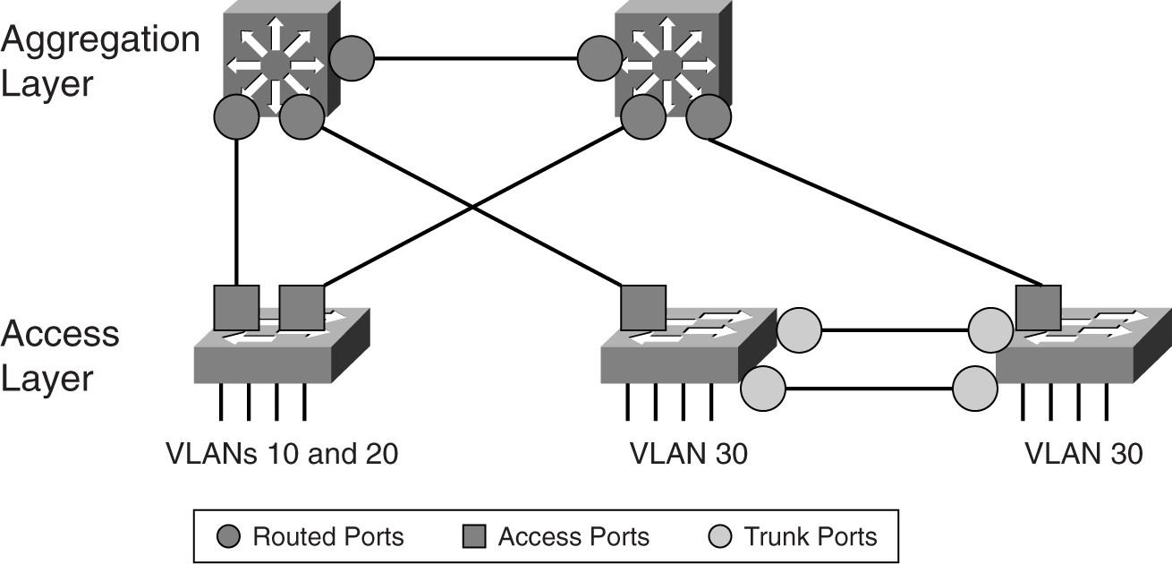
One drawback of this design is the restricted footprint of the VLANs. Placing a pair of fault-tolerant servers that use a Layer 2 network for a heartbeat is challenging. For example, if you want to place one of the servers in another location, the Layer 2 network has to be expanded in an awkward manner, as shown in [Figure 9-16](https://learning.oreilly.com/library/view/building-resilient-ip/1587052156/ch09.html#ch09fig16).
**Figure 9-16** _Extending the Access Layer_
As with application layer design, both access layer design options have pros and cons. You may use a mix of both within a data center.
#### Architecture Scaling Consideration
Although the focus of a server farm design still revolves around switching and routing technology, many network managers mistake the design as just another typical campus design. Besides those differences discussed in the section “[Data Center Network Considerations](https://learning.oreilly.com/library/view/building-resilient-ip/1587052156/ch09.html#ch09sec1lev2),” one more factor makes designing a server farm different from a campus design: scaling.
A server farm has a unique scaling challenge simply because of bandwidth requirements. Unlike user workstations, which tend to be idle most of the time and generate bursty traffic at other times, server traffic tends to be consistently high volume. Therefore, it is easy to hit a performance issue in the server farm just because of bandwidth. [Figure 9-17](https://learning.oreilly.com/library/view/building-resilient-ip/1587052156/ch09.html#ch09fig17) shows one good example of a scaling problem.
**Figure 9-17** _Scaling a High-Density Server Farm_
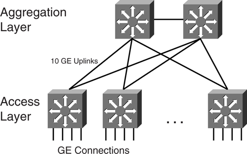
In [Figure 9-17](https://learning.oreilly.com/library/view/building-resilient-ip/1587052156/ch09.html#ch09fig17), the server farm architecture makes use of the chassis-based access layer to provide connections for the servers. Suppose that all the servers are connected at gigabit speed, and they are all capable of generating line-rate traffic. Because of the number of servers connecting to a single access switch, the network manager has decided to adopt 10 GE as the uplink standard. Now consider the number of 10 GE ports that are required on the aggregating device. You soon realize that aggregating traffic at such a speed requires a reevaluation of the hardware architecture of the aggregating devices, as well as the network design. Not many switches can support a high density of 10-GE ports. In addition, it would seem a waste of expensive resources to prevent a 10-GE uplink from forwarding traffic just because of an STP-blocked mode. Therefore, not only the hardware needs to be reevaluated to support the bandwidth required, the logical network design needs to be revisited, too. There is certainly a need to create many aggregating modules to scale the server farm.
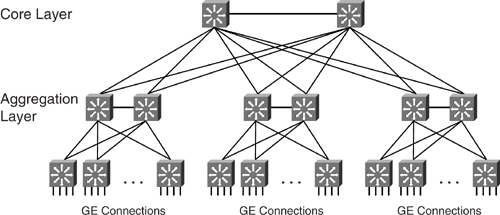
Integrating all the aggregating modules into a common data center may mean introducing another layer. For the convenience of this discussion, this new layer is called the _core layer within the data center_. Most network managers probably have not had an opportunity to work on such a scale. Such a design is usually found in extremely huge data centers with thousands of servers. The core layer within the data center functions in the same way as an IP core network module: it consolidates individual blocks. In this case, the individual blocks are the aggregating layers, each with hundreds of servers generating huge traffic loads, as shown in [Figure 9-18](https://learning.oreilly.com/library/view/building-resilient-ip/1587052156/ch09.html#ch09fig18).
**Figure 9-18** _Core Layer Within a Data Center Module_
### Data Center Network Security
Unlike the old days when security meant planting one or two firewalls, data center security today takes on a different dimension. With information playing a vital role in the operation of a business, the stakes are getting too high for information to be compromised. Attacks on networks are becoming more sophisticated and they are done through, but not limited to, the following techniques:
• **Packet sniffing**—An application that uses the promiscuous mode of the network adapter to capture all networks packets.
• **IP spoofing**—An attack in which a hacker assumes an IP address of others to conceal its true identity.
• **Denial-of-service (DoS) attack**—Aims to overwhelm a service so as to deny legitimate requests from being serviced. The service may be in the form of bandwidth, memory, or CPU. It is the most well-known of all Internet attacks, and efforts should be invested in understanding its mechanisms. Some of the more famous DoS attacks include the following:
—Code Red
—Blaster
—Ping of Death
—Trinity
• **Password attack**—As its name implies, this attack intends to acquire passwords to important assets so as to cause further damage. Password attacks can be achieved through other methods previously mentioned, such as IP spoofing, or they can be achieved via brute force.
• **Man-in-the-middle attack**—This type of attack happens when a hacker manages to position himself between the source and the destination of a network transaction. ARP cache poisoning is one common method.
• **Application attack**—This type of attack happens when application software holes are exploited to gain access to a computer system. The holes may be bugs or may be TCP port numbers that are exposed.
• **Port redirection attack**—This type of attack makes use of a compromised host to gain access to a network that is otherwise protected.
Understanding the mechanics of all these attacks is important, so that you know what you are up against. Such an understanding also helps you decide how the architecture should look, and what features are required in those routers and switches within the data center. In general, attacks can be launched from Layer 2 or Layer 3 perspectives, and each layer has to have some defense mechanism built in to the architecture. No longer can a network manager treat security as an afterthought. Instead, security should be an integral part of the data center architecture.
#### Layer 2 Security
Layer 2 security deals with protecting the network and hosts at the MAC level. [Figure 9-19](https://learning.oreilly.com/library/view/building-resilient-ip/1587052156/ch09.html#ch09fig19) shows a simple attacking mechanism that can compromise a Layer 2 network.
**Figure 9-19** _Worm Attack on the Server_
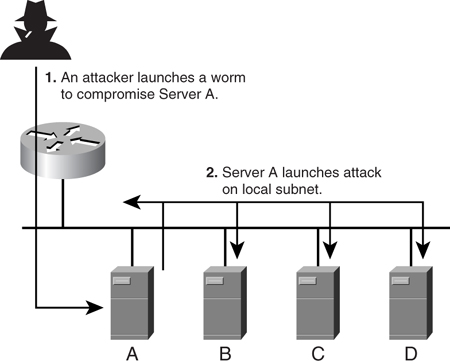
In [Figure 9-19](https://learning.oreilly.com/library/view/building-resilient-ip/1587052156/ch09.html#ch09fig19), Server A has been compromised by a worm from outside the network. When the worm strikes, it starts sending out probe packets and generating broadcast storms on the local subnet. The probe packets enable Server A to further infect other hosts, while the broadcast storm consumes all bandwidth on the subnet. This form of worm attack is the simplest to execute, but its damage can prove substantial.
One way to counter this sort of attack is to isolate the servers into different broadcast domains. With a Layer 3 partition, chances of a broadcast storm are minimized because there are fewer servers and they are protected from each other. However, this means using more subnets and, thus, wasting precious IP addresses. For example, in the most drastic implementation, you could put one server in a single IP subnet with its own default gateway. That means wasting four addresses, a /30 subnet, just to provide connectivity to a single server. In addition, a /30 subnet also means there are not enough IP addresses on the subnet to provide for a redundant gateway. When there is a shortage of public IP addresses, this might not be a good solution. Perhaps you need a solution that segregates the servers at the Layer 2 level while allowing them to share a common IP subnet. This is where the concept of private VLANs (PVLANs) comes in.
##### Private VLANs (PVLANs)
The PVLAN feature aims to solve the Layer 2 broadcast attack problem (and work around the IP address shortage issue).
The basic concept of a PVLAN is simple. It provides Layer 2 isolation for a group of hosts residing in the same IP subnet, as illustrated in [Figure 9-20](https://learning.oreilly.com/library/view/building-resilient-ip/1587052156/ch09.html#ch09fig20).
**Figure 9-20** _Private VLAN_
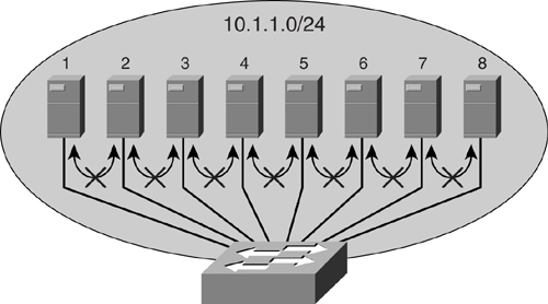
In [Figure 9-20](https://learning.oreilly.com/library/view/building-resilient-ip/1587052156/ch09.html#ch09fig20), all the servers reside within the same subnet (in this case, a /24 network). They share the same default gateway, and from a networking perspective, this is the only common entity that they can connect to. Although they reside within the same IP subnet, they have been isolated from a Layer 2 perspective. Every server behaves as if there are only two hosts on their subnet—itself and its default gateway. All communication at the Layer 2, be it broadcast or multicast, has been isolated for these servers.
With this implementation, even if one server is compromised, just as before, it will not be able to launch an attack on the rest of the servers. The probe packet will not get to the rest of the servers, and the broadcast will be contained, too. The only probable target is its default gateway. In this case, proper security measures and configuration would have been implemented on the default gateway to deal with attacks such as this.
In some cases, because of fault-tolerance requirements, certain groups of servers may need to communicate with each other via Layer 2 connectivity. In this case, PVLAN provides the concept of a community, where only servers within this community have Layer 2 communication. As a community, these servers are Layer 2 isolated from the rest of the servers within the same PVLAN. Thus, PVLAN provides protection but still allows servers to run in a fault-tolerant manner.
To support this community feature, the PVLAN feature introduces a new port role and VLAN concepts. To configure PVLAN, it is important that you understand these roles.
###### PVLAN Ports
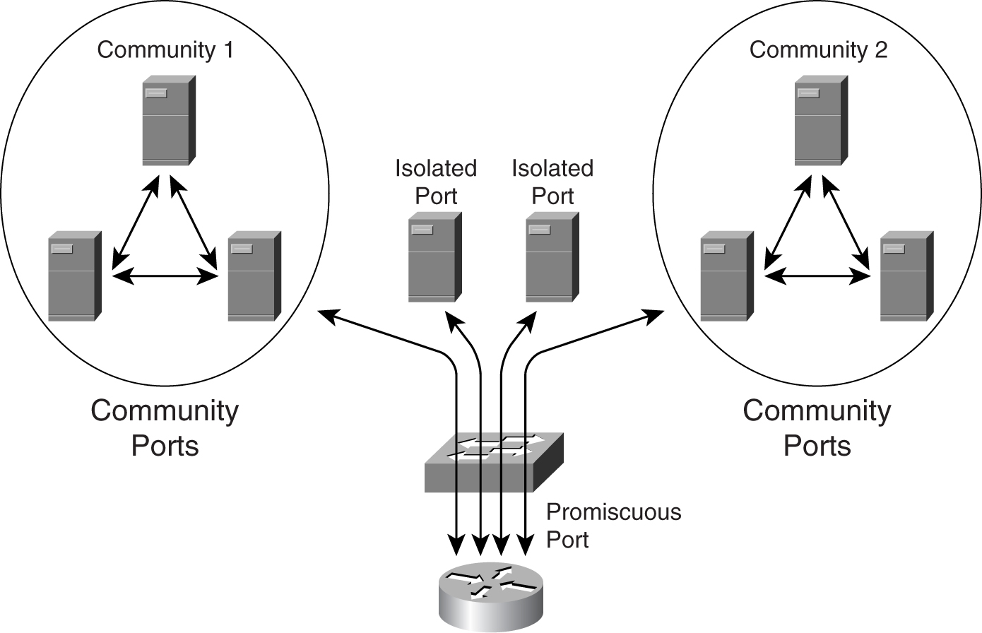
There are three types of PVLAN ports:
• **Promiscuous port**—This port can communicate with all other ports within a PVLAN. This is where the default gateway for the IP subnet resides.
• **Isolated port**—This port is completely isolated from the rest of the PVLAN ports, except the promiscuous port.
• **Community ports**—These ports can communicate among themselves at Layer 2. They are separated from other community ports or isolated ports, except the promiscuous port.
[Figure 9-21](https://learning.oreilly.com/library/view/building-resilient-ip/1587052156/ch09.html#ch09fig21) shows the relationship of the three port types.
**Figure 9-21** _Port Types of the Private VLAN_
###### Types of VLANs
The PVLAN feature is achieved via the combination of a few special VLANs. These VLANs have to be created first before the PVLAN feature can actually work:
• **Primary VLAN**—The VLAN that carries traffic from the promiscuous port to all other ports.
• **Isolated VLAN**—The VLAN used by the isolated port to communicate with the promiscuous port. There can be multiple isolated VLANs within a PVLAN.
• **Community VLAN**—The VLAN used by the community ports to communicate among themselves and to send traffic to the promiscuous port. There can be multiple community VLANs within a PVLAN.
Note
Both the isolated and community VLANs are also known as _secondary VLANs_.
The construction of a PVLAN allows for these VLANs to be trunked across multiple switches as long as they support the PVLAN feature.
###### Configuring PVLAN
PVLAN configuration requires a few steps. [Figure 9-22](https://learning.oreilly.com/library/view/building-resilient-ip/1587052156/ch09.html#ch09fig22) shows a PVLAN configuration.
**Figure 9-22** _Example of a Private VLAN_
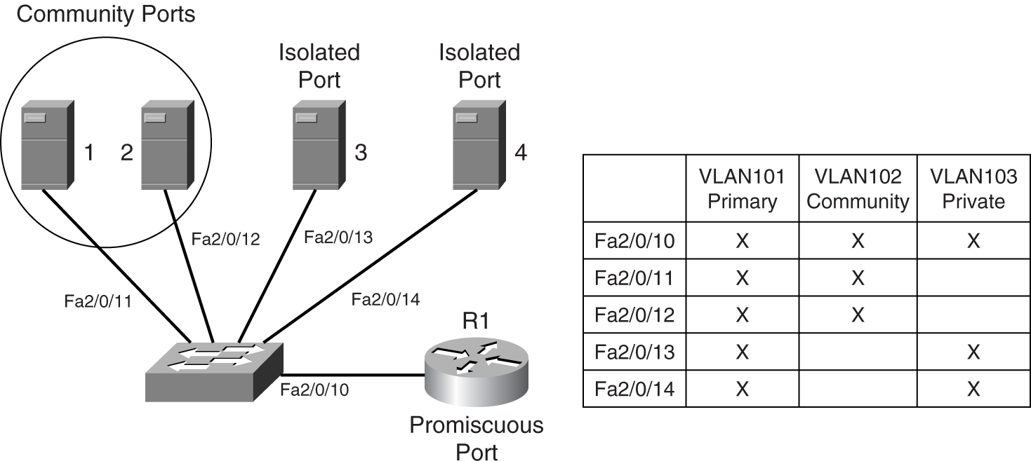
Suppose you are required to construct the PVLAN shown in [Figure 9-22](https://learning.oreilly.com/library/view/building-resilient-ip/1587052156/ch09.html#ch09fig22). Servers 1, 2, 3, and 4 reside within a PVLAN, where their traffic is isolated at Layer 2. Servers 1 and 2 reside within a community, because they run fault-tolerant features that require Layer 2 connectivity. All the servers share the same default gateway, which is R1.
[Example 9-1](https://learning.oreilly.com/library/view/building-resilient-ip/1587052156/ch09.html#ch09ex01) shows the steps to create the required PVLAN:
**Step 1** Create a primary VLAN, VLAN101.
**Step 2** Create a community VLAN, VLAN102.
**Step 3** Create an isolated VLAN, VLAN103.
**Step 4** Associate the secondary VLANs to the primary VLAN.
**Step 5** Configure switch port Fa2/0/10 as a PVLAN promiscuous port.
**Step 6** Configure switch ports Fa2/0/11 as PVLAN host ports. A host port is a switch port that participates in a PVLAN, but it is not the promiscuous port. The configuration for Fa2/0/12 to Fa2/0/14 will be the same except for their respective PVLAN assignments.
**Example 9-1** _Creating a Private VLAN_
---
Step 1
Switch# configure terminal
Switch(config)# vlan 101
Switch(config-vlan)# private-vlan primary
Switch(config-vlan)# end
Switch# show vlan private-vlan
Primary Secondary Type Interfaces
------- --------- ----------------- -----------------------------------
101 primary
Step 2
Switch# configure terminal
Switch(config)# vlan 102
Switch(config-vlan)# private-vlan community
Switch(config-vlan)# end
Switch# show vlan private-vlan
Primary Secondary Type Interfaces
------- --------- ----------------- -----------------------------------
101 primary
102 community
Step 3
Switch# configure terminal
Switch(config)# vlan 103
Switch(config-vlan)# private-vlan isolated
Switch(config-vlan)# end
Switch# show vlan private-vlan
Primary Secondary Type Interfaces
------- --------- ----------------- -----------------------------------
101 primary
102 community
103 isolated
Step 4
Switch# configure terminal
Switch(config)# vlan 101
Switch(config-vlan)# private-vlan association 102-103
Switch(config-vlan)# end
Switch# show vlan private-vlan
Primary Secondary Type Interfaces
------- --------- ----------------- ----------------------------------
101 102 community
101 103 isolated
Step 5
Switch# configure terminal
Switch(config)# interface fastethernet 2/0/10
Switch(config-if)# switchport mode private-vlan promiscuous
Switch(config-if)# switchport private-vlan mapping 101 add 102-103
Switch(config-if)# end
Switch#show interfaces fastethernet 2/0/10 switchport
Name: Fa2/0/10
Switchport: Enabled
Administrative Mode: private-vlan promiscuous
Operational Mode: private-vlan promiscuous
Administrative Trunking Encapsulation: negotiate
Negotiation of Trunking: Off
Access Mode VLAN: 1 (default)
Trunking Native Mode VLAN: 1 (default)
Administrative Native VLAN tagging: enabled
Voice VLAN: none
Administrative private-vlan host-association: none
Administrative private-vlan mapping: 101 (VLAN101) 102 (VLAN102) 103 (VLAN103)
Administrative private-vlan trunk native VLAN: none
Administrative private-vlan trunk Native VLAN tagging: enabled
Administrative private-vlan trunk encapsulation: dot1q
Administrative private-vlan trunk normal VLANs: none
Administrative private-vlan trunk private VLANs: none
Operational private-vlan:
101 (VLAN101) 102 (VLAN102) 103 (VLAN103)
Trunking VLANs Enabled: ALL
Pruning VLANs Enabled: 2-1001
Capture Mode Disabled
Capture VLANs Allowed: ALL
Step 6
Switch# configure terminal
Switch(config)# interface fastethernet 2/0/11
Switch(config-if)# switchport mode private-vlan host
Switch(config-if)# switchport private-vlan host-association 101 102
Switch(config-if)# end
Switch#show interfaces fastethernet 2/0/11 switchport
Name: Fa2/0/11
Switchport: Enabled
Administrative Mode: private-vlan promiscuous
Operational Mode: private-vlan promiscuous
Administrative Trunking Encapsulation: negotiate
Negotiation of Trunking: Off
Access Mode VLAN: 1 (default)
Trunking Native Mode VLAN: 1 (default)
Administrative Native VLAN tagging: enabled
Voice VLAN: none
Administrative private-vlan host-association: none
Administrative private-vlan mapping: 101 (VLAN101) 102 (VLAN102)
Administrative private-vlan trunk native VLAN: none
Administrative private-vlan trunk Native VLAN tagging: enabled
Administrative private-vlan trunk encapsulation: dot1q
Administrative private-vlan trunk normal VLANs: none
Administrative private-vlan trunk private VLANs: none
Operational private-vlan:
101 (VLAN101) 102 (VLAN102)
Trunking VLANs Enabled: ALL
Pruning VLANs Enabled: 2-1001
Capture Mode Disabled
Capture VLANs Allowed: ALL
---
As you can see from Step 5’s **show** command in [Example 9-1](https://learning.oreilly.com/library/view/building-resilient-ip/1587052156/ch09.html#ch09ex01), port Fa2/0/10 is associated with VLANs 101, 102, and 103, indicating that it is a promiscuous port. Step 6’s **show** command shows Fa2/0/11 associated with the two VLANs, 101 and 102, indicating that it is a host port.
###### Catalyst Support for PVLANs
Note that not all Catalyst switches support the PVLAN feature. Those that do not support the PVLAN feature may support a subset of the PVLAN feature called the _PVLAN edge function_.
The PVLAN edge function provides port isolation on a per-switch basis. There is no protection between isolated ports on different switches. As in the isolated ports of the PVLAN feature, the PVLAN edge ports do not forward traffic to any other ports.
[Table 9-1](https://learning.oreilly.com/library/view/building-resilient-ip/1587052156/ch09.html#ch09tab01) shows the list of PVLAN features supported by the Catalyst range of products.
**Table 9-1** _Range of Catalyst Switches Supporting Private VLANs_

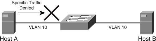
##### VLAN Access Control List (VACL)
A VLAN access control list (VACL) is another feature that assists in preventing attacks from taking place at Layer 2. This feature allows access lists to be applied at the VLAN level. This is different from the traditional access list, which is applied at the Layer 3 level. Together with the PVLAN feature, a VACL enables network managers to exert powerful control over the security of the server farm. [Figure 9-23](https://learning.oreilly.com/library/view/building-resilient-ip/1587052156/ch09.html#ch09fig23) shows an example VACL, where Host A is not allowed to send specific traffic to Host B.
**Figure 9-23** _VLAN Access Control List_
As mentioned in the section “[Private VLAN](https://learning.oreilly.com/library/view/building-resilient-ip/1587052156/ch09.html#ch09sec3lev8),” the PVLAN is made up of multiple VLANs functioning together. The traffic from the default gateway travels in one direction via the primary VLAN. Traffic from the servers travels via the secondary VLANs to the default gateway.
A VACL can be applied on the secondary VLANs only, without affecting the primary VLAN. This way, traffic from the default gateway to the servers is not affected at all, whereas traffic from the servers is subjected to further inspection. It is also possible to filter traffic on the isolated VLAN, while leaving the community VLAN untouched.
The combination of PVLAN and VACL is a powerful tool in fighting Layer 2 attacks. For example, because a server is set up to receive connection requests, it is rare for it to be initiating a high volume of requests. Under a worm attack, it is common to see servers initiating hundreds, if not thousands, of connection requests. Therefore, a VACL can be applied on the secondary VLAN so that all connections originating from the server are dropped. This way, the attack can be minimized, and the spread of the worm attack can be contained.
A VACL is implemented in hardware on the Catalyst 6500 series switches. The VACLs are configured at Layer 2 and, therefore, need only the PFC module to operate. Because the function is implemented in hardware, the performance of the switch remains the same regardless of the size of the ACL.
##### Port Security
Port security blocks access to a switch port based on MAC addresses. This happens when the MAC address of the station attempting to access the port differs from the list of MAC addresses that is specified for the port. The list of allowed MAC addresses can be manually keyed in or learned dynamically.
When a security violation occurs, the switch port can either be shut down permanently or only for a period of time. The port can also operate in a restrictive mode in which it drops traffic only from an offending station.
[Example 9-2](https://learning.oreilly.com/library/view/building-resilient-ip/1587052156/ch09.html#ch09ex02) shows the configuration of port security on the Catalyst 6500 switch.
**Example 9-2** _Configuring Port Security_
---
Console> (enable) set port security 2/1 enable
Port 2/1 security enabled.
Console> (enable) show port 2/1
Port Name Status Vlan Level Duplex Speed Type
----- ------------------ ---------- ---------- ------ ------ ----- ------------
2/1 connected 522 normal half 100 100BaseTX
Port Security Secure-Src-Addr Last-Src-Addr Shutdown Trap IfIndex
----- -------- ----------------- ----------------- -------- -------- -------
2/1 enabled 00-90-2b-03-34-08 00-90-2b-03-34-08 No disabled 1081
Port Broadcast-Limit Broadcast-Drop
-------- --------------- --------------
2/1 - 0
Port Align-Err FCS-Err Xmit-Err Rcv-Err UnderSize
----- ---------- ---------- ---------- ---------- ---------
2/1 0 0 0 0 0
Port Single-Col Multi-Coll Late-Coll Excess-Col Carri-Sen Runts Giants
----- ---------- ---------- ---------- ---------- --------- --------- ---------
2/1 0 0 0 0 0 0 0
Last-Time-Cleared
--------------------------
Fri 8 April 2005, 12:50:38
---
Port security helps mitigate attacks where a host is compromised, and the worm is generating bogus MAC addresses to flood the network.
##### Dynamic ARP Inspection
A man-in-the-middle attack makes use of the ARP protocol to insert itself in the middle of a conversation. _ARP cache poisoning_ is a common example. To prevent such attacks from taking place, switches must ensure that only valid ARP requests and responses are forwarded. Dynamic ARP inspection works by intercepting all ARP packets and verifying that valid MAC and IP address bindings are taking place.
The dynamic ARP inspection feature determines the validity of the ARP packets by inspecting its database. This database contains information obtained from the Dynamic Host Configuration Protocol (DHCP) operation, or it may be configured manually for server connections.
When invalid ARP packets are detected in the network, the dynamic ARP inspection feature causes the switch to drop the packet. The feature also rate limits the ARP packets, such that anything above the preset threshold may be deemed a DoS attack. All ports that are connected to an end device are considered untrusted, and are therefore subject to the inspection. Ports that are connected to other switches are considered trusted and will not be inspected, because it is assumed that the traffic would have been inspected by other switches already.
[Example 9-3](https://learning.oreilly.com/library/view/building-resilient-ip/1587052156/ch09.html#ch09ex03) shows an example of configuring a dynamic ARP inspection.
**Example 9-3** _Configuring a Dynamic ARP Inspection_
---
Switch# configure terminal
Enter configuration commands, one per line. End with CNTL/Z.
Switch(config)# ip arp inspection vlan 10
Switch(config)# end
Switch# show ip arp inspection vlan 10
Source Mac Validation : Disabled
Destination Mac Validation : Disabled
IP Address Validation : Disabled
Vlan Configuration Operation ACL Match Static ACL
---- ------------- --------- --------- ----------
10 Enabled Active
Vlan ACL Logging DHCP Logging
---- ----------- ------------
10 Deny Deny
Switch#
Switch# configure terminal
Enter configuration commands, one per line. End with CNTL/Z.
Switch(config)# interface fa6/3
Switch(config-if)# ip arp inspection trust
Switch(config-if)# end
Switch# show ip arp inspection interfaces fastEthernet 6/3
Interface Trust State Rate (pps)
--------------- ----------- ----------
Fa6/3 Trusted None
Switch#
---
The examples given so far demonstrate the importance of Layer 2 security within the data center network. Because it is difficult to rework the network just to implement some of these features, you must build them in to the design from day one.
#### Layer 3 Security
Traditionally, Layer 3 security has been a task performed by firewalls. Firewalls inspect IP packets and TCP sessions to determine whether traffic is “safe” and, therefore, should be allowed to continue its path into the network. Firewalls are essential in preventing attacks such as IP address spoofing, port scans, TCP SYNC packet flooding, and so on. It can be considered as the single point of entry to the information required and plays a vital role in maintaining the network perimeter security.
However, security is no longer just about firewalls anymore. The sophistication of attacks has evolved, and you need more than just a firewall to protect the critical resources within the server farm. No longer is the attacker just coming from outside the network; it could very well be an insider job nowadays. In addition, the trend in attacking has moved from application server to infrastructure attack. These attacks are sophisticated and require network managers to have a solid understanding of IP technology to appreciate the danger (and to know how to mitigate these threats).
##### Switch Forwarding Architecture
As mentioned in the section “[Adopt Topology-Based Switching](https://learning.oreilly.com/library/view/building-resilient-ip/1587052156/ch06.html#ch06sec3lev22)” in [Chapter 6](https://learning.oreilly.com/library/view/building-resilient-ip/1587052156/ch06.html#ch06), switching hardware architecture can be exploited to bring down a network. This is especially so in the data center, where a high concentration of servers means there are many switches to exploit. When a server is infected by a worm, its high-performance network interface can be a deadly tool if it starts generating hundreds or thousands of flows per second. As recommended in [Chapter 6](https://learning.oreilly.com/library/view/building-resilient-ip/1587052156/ch06.html#ch06), a topology-based switching architecture should be adopted for all switches in the data center.
##### Control Plane Policing
As mentioned in the section “[Control Plane Policing](https://learning.oreilly.com/library/view/building-resilient-ip/1587052156/ch09.html#ch09sec3lev13)” in [Chapter 4](https://learning.oreilly.com/library/view/building-resilient-ip/1587052156/ch04.html#ch04), “[Quality of Service](https://learning.oreilly.com/library/view/building-resilient-ip/1587052156/ch04.html#ch04),” it is important to protect the control plane of the switches. This is especially important for the switches in the data center, because the consequence of a switch failure can mean taking many servers out of service. This feature is especially important for switches that serve the DMZ network, because the servers in the DMZ network are accessible from outside the network and therefore have a higher chance of being compromised.
##### DHCP Server Protection
A DHCP server is used widely to assign IP addresses to clients in a network in both enterprise and service provider networks. It is one of the most critical assets within an IP infrastructure. However, its importance is sometimes overlooked, because network managers pay more attention to protecting application servers.
A compromised DHCP server can mean networkwide outages, because the server can no longer assign IP addresses to the clients. Without an IP address, there will be no more network connections for new users who have just joined the network.
A DHCP server can be compromised easily. In [Figure 9-24](https://learning.oreilly.com/library/view/building-resilient-ip/1587052156/ch09.html#ch09fig24), a hacker launches an attack on the DHCP server just by generating a high number of DHCP requests. The DHCP server quickly runs out of IP addresses from its pools. Legitimate users who now try to log in to the network find that there is no connection, because no IP addresses are being assigned.
**Figure 9-24** _Attacking a DHCP Server_
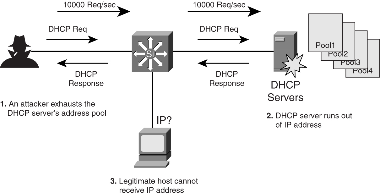
DHCP snooping is a security feature that filters untrusted DHCP messages such as those shown in [Figure 9-24](https://learning.oreilly.com/library/view/building-resilient-ip/1587052156/ch09.html#ch09fig24). Untrusted DHCP messages may originate from outside the network or from some compromised hosts within the network. The feature enforces security by building and maintaining a DHCP binding table. The table contains important information such as the MAC address, IP address, leased time, and VLAN number. With the information from the table, the feature acts like a firewall between untrusted hosts and the DHCP server.
[Example 9-4](https://learning.oreilly.com/library/view/building-resilient-ip/1587052156/ch09.html#ch09ex04) shows an example of configuring the DHCP snooping feature.
**Example 9-4** _Configuring DHCP Snooping_
---
Switch(config)# ip dhcp snooping
Switch(config)# ip dhcp snooping vlan 100
Switch(config)# ip dhcp snooping information option
Switch(config)# interface fastethernet0/10
Switch(config-if)# ip dhcp snooping limit rate 50
---
In [Example 9-4](https://learning.oreilly.com/library/view/building-resilient-ip/1587052156/ch09.html#ch09ex04), the switch has the DHCP snooping function enabled on VLAN 100. It is also enforcing a rate limit of 50 packets per second on one of its ports.
### Service Optimization
In the discussion of a resilient IP network, much of the focus is on the network itself, like designing the IP network for resiliency, deploying resilient hardware in a network, and enabling protocols in the network to protect from failure.
However, there is one area, called _service optimization_, that is critical to the whole resilient IP network equation, but it is not familiar territory for many network managers. Service optimization is beyond having a resilient IP network where connectivity is always available. More important, it is about highly available information, delivered in an optimized way.
Because information derives from the server farm, service optimization is about designing a server farm infrastructure such that it is fault tolerant, secured, and scalable. For example, when a company announces an online price-reduction promotion, its website can be easily overwhelmed by the sudden influx of requests, called _flash crowds_, if the server farm is not optimized for this service. So, although the IP network may still be up and running, it is not serving its purpose, because it cannot process those requests.
Special features have been developed to solve flash crowd problems, including the following:
• [Server load balancing](https://learning.oreilly.com/library/view/building-resilient-ip/1587052156/ch09.html#ch09sec2lev15)
• [Global site selector](https://learning.oreilly.com/library/view/building-resilient-ip/1587052156/ch09.html#ch09sec2lev16)
• Web caching
• Integrated service module
These features play an important part in the overall availability of information, and they are unique to the data center module.
#### Server Load Balancing
Server load balancing (SLB), sometimes known as _content switching_, is about server virtualization. The aim of SLB is to combine the processing power of various servers into one huge virtual server that provides information in a nonstop fashion. This is partly to mitigate the risk of losing a single server, and partly to improve the performance by having more horsepower. Another benefit of SLB is that maintenance can be performed on a single server while the rest continue to provide the information. To the clients, this virtual server behaves as if it is one huge physical server. Although many server vendors have their own high-availability architecture, they are usually proprietary in nature and costly. A network-based SLB architecture enables network managers to tackle the same problem in another way.
[Figure 9-25](https://learning.oreilly.com/library/view/building-resilient-ip/1587052156/ch09.html#ch09fig25) shows the concept of SLB. Three physical servers are connected to a router running the SLB function. These servers appear to the outside world as one virtual server with the URL [http://www.acme.com](http://www.acme.com/) and an associated virtual IP address.
**Figure 9-25** _Server Load Balancing_
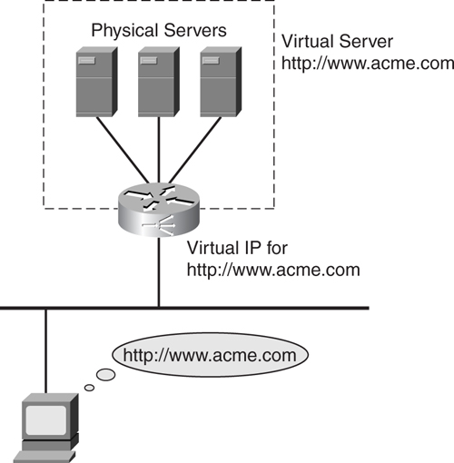
In a nutshell, SLB works by having the router or an SLB appliance intercepting all requests to a website. Based on the type of request, it then selectively assigns the physical servers located behind it to process those requests.
To understand how SLB technology works, you need to understand several critical concepts. These concepts, called _policies_, dictate how SLB will be configured and how applications will be handled:
• **Load-balancing policies**—These rules dictate how connections are distributed across the physical servers. Load-balancing policies are usually called the load-distribution algorithms, which include the following:
—Round robin—Assigned in sequential manner, going back to the first server after the last one has been assigned.
—Weighted round robin—Same as round robin, except weights can be assigned so that some servers can be serving more requests.
—Least connections—The one with the least connections gets assigned.
—Weighted least connections—Same as least connections, except weights can be assigned to influence the next in line.
—Least loaded—Assigned based on server load.
—Hashing—Based on information such as a source IP address or URL.
• **Persistence policies**—These rules describe requirements to ensure that requests coming to a particular physical server are maintained until web transactions, or sessions, have completed. For the SLB device to keep track of these sessions, some form of identification has to be present in the traffic stream. This information is typically found within the URL, cookie, or the SSL session ID of the request
• **Server failure policies**—These rules dictate the error-handling mechanism when a physical server fails. The server may be in the process of a web transaction. In this case, there are several ways to work around this failure:
—Restart the transaction
—Redirect the session to another server
—Issue an error message from another server
• **Content-specific policies**—These rules may be implemented to direct traffic based on its content type. For example, you may want to route a request for general information to a particular server, whereas the request for an application transaction may be rerouted to another server, because application transactions require a more powerful server.
• **Device-specific policies**—These rules direct traffic based on the device types of the requestor. For example, a request from a PC browser may be directed to a particular server, whereas a request from PDA device may be directed to another server.
The physical servers reside behind the SLB device, and these are the resources that process those requests. When directing requests to these physical servers, the SLB device may modify the request packets, depending on whether the requests are forwarded to the servers through directed mode or dispatch mode.
In _directed mode_, the SLB device forwards the traffic via Network Address Translation (NAT). In this case, the destination address in the request, which is pointing to the virtual IP address residing in the SLB device, is translated to the IP address of the assigned physical server. The MAC address of the packet is also rewritten.
In _dispatch mode_, only the MAC address is rewritten; the original destination IP address is preserved. Dispatch mode proves especially useful in the scenario when the SLB device is actually load-balancing firewalls, which requires the IP address to be preserved. Depending on implementation details, other information within the packet, such as the source IP address, TCP ports, and checksums, may be modified.
Based on the SLB polices, it is possible to devise a rule for all requests that contain the following information:
Destination IP = 10.1.1.1
Protocol = TCP
Destination port = 80
Send the request to the following two servers, using a round-robin algorithm:
10.2.1.1, port 80
10.2.1.2, port 80
In this scenario, the load-balancing decision is made based on IP address, protocol, and TCP port number. Because this Layer 3 and 4 information is available, redirection can be done right from the start of the TCP connection, within the TCP SYNC packet.
It is also possible to load balance based on more complex criteria, such as the following:
Destination IP = 10.1.1.1
Protocol = TCP
Destination port = 80
URL contains ApplicationForCarLoan.html
Send the request to the following two servers, using a round-robin algorithm:
10.2.1.1, port 80
10.2.1.2, port 80
For this scenario, information provided by the TCP SYNC packet alone will not be enough for the redirection to take place. Because the content switch needs to base its decision on URL content, it must be able to read into the request first. However, the client will not send the URL request until it has terminated its TCP SYNC request. To overcome this deadlock, the SLB device needs the feature called _delayed binding_.
[Figure 9-26](https://learning.oreilly.com/library/view/building-resilient-ip/1587052156/ch09.html#ch09fig26) shows the concept of delayed binding in SLB. Unlike a direct TCP connection between a client and a server, delayed binding consists of two connections: a front end and a back end. The front-end connection consists of the client and the virtual IP address of the intended destination, which resides in the SLB device. The back-end connection is established between the SLB device and the actual server. The following steps are involved in delayed binding:
**1** Client sends TCP SYNC request to the virtual IP address.
**2** SLB device returns TCP SYNC/ACK to client.
**3** Client sends TCP ACK to SLB device; TCP connection established.
**4** Client sends HTTP Get request, which contains the URL of the web page that it is requesting. SLB device looks into the URL and decides to which server to send the request.
**5** SLB sends TCP SYNC request to the assigned server.
**6** Assigned server returns TCP SYNC/ACK to SLB device.
**7** SLB device sends TCP ACK to assigned server, TCP connection established
**8** SLB device sends the HTTP Get request to the assigned server for processing.
**Figure 9-26** _TCP Delayed Binding_
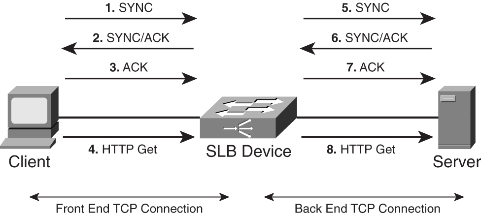
Via delayed binding, the SLB device acts as a middleman between the client and the actual server. To maintain the connectivity, the SLB device spliced both the front end and the back end together via some data structure. This way, it can keep track of which front-end connection is to be linked to which back-end connection.
SLB can be thought of as the network’s way of improving information availability. It is a critical component within a resilient IP architecture, because availability of information is what counts. You might be able to build a resilient IP network, but without robust information availability, the network might not serve its purpose.
The SLB function is delivered via the Cisco CSS 11500 family of content switches. For high-performance SLB functionality, consider the Catalyst 6500 Content Switching Module (CSM).
#### Global Site Selector
SLB protects the network infrastructure from a physical server failure by having multiple servers working on the requests; however, it does not protect the infrastructure from a site failure. In the event that a catastrophic event happens to the entire rack containing the servers, or worse, the entire data center, users will not be able to obtain the information that they want. The global server load balancing (GSLB) technique aims to solve this problem. Whereas SLB works by load balancing traffic across servers, GSLB works by load balancing traffic across geographically dispersed data centers.
The function of GSLB is delivered via a product called the _Global Site Selector_ (_GSS_). The GSS is an integral part of the DNS routing hierarchy, and works closely with the SLB devices such as the Cisco CSS 11500 family of switches or the CSM service module on the Catalyst 6500 series. The GSS improves the availability of information in the following ways:
• Monitors the health of the SLB devices, and based on a customized policies, directs user requests to an alternate SLB device.
• Detects site outages, and redirects user requests to another data center for continued processing of information.
• Sends requests to the nearest site for faster processing.
• Offloads the traditional DNS server by taking over the resolution process at a request rate of thousands per second. Because DNS resolution constitutes a major portion of delay in web traffic, an improvement in this process improves latency and cuts down response time from a user perspective.
Before you can use the GSS effectively, you must have a good understanding of the DNS resolution process.
##### Understanding DNS Resolution
The Domain Name System (DNS) is a distributed database of host information that maps domain names to IP addresses for the Internet. It has been used since the early 1980s, and almost all applications on the Internet today rely on DNS, including HTTP, FTP, Telnet, e-mail, and so on. With DNS, there is no need to remember the IP address of the Cisco Systems website, for example. You just need to remember [www.cisco.com](http://www.cisco.com/).
[Figure 9-27](https://learning.oreilly.com/library/view/building-resilient-ip/1587052156/ch09.html#ch09fig27) shows how [www.cisco.com](http://www.cisco.com/) fits in the DNS structure. Just like a file system, the DNS structure is hierarchical and is made up of the following components:
• **DNS resolver (DNSR)**—Clients that access client name servers.
• **Client name server (CNS)**—A server running DNS software and is responsible for finding the requested website. CNS is also known as DNS proxy (D-Proxy).
• **Root name server (RNS)**—A server that resides at the top of the DNS hierarchy. These are the servers that hold the entire DNS database. There are 13 root servers in the Internet today.
• **Authoritative name server (ANS)**—A server that is run by an enterprise or a service provider. This server is the authoritative server for the domain requested. The ANS responds to the CNS with the requested IP address. It does not respond to the client directly.
• **Intermediate name server (INS)**—A server that is used for scaling the DNS infrastructure. When the RNS does not have the IP address of the ANS, it sends the requesting CNS to an INS. The INS then sends the CNS to the ANS.
**Figure 9-27** _DNS Structure_
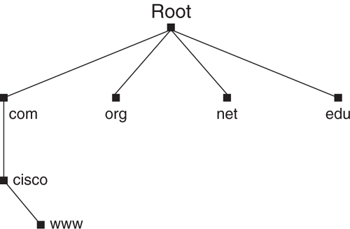
One important aspect of DNS is the process known as _delegation_. Delegation enables a network manager to locally administer the segments, or domains, yet makes it possible for the information to be made available to the entire Internet.
As illustrated in [Figure 9-28](https://learning.oreilly.com/library/view/building-resilient-ip/1587052156/ch09.html#ch09fig28), the DNS resolution process for [www.cisco.com](http://www.cisco.com/) goes through the following steps:
**Step 1** The client sends a request to the CNS for the IP address of [www.cisco.com](http://www.cisco.com/).
**Step 2** The CNS can either reply with an IP address, if it already knows the IP address of [www.cisco.com](http://www.cisco.com/), or it will send a request to the RNS (Step 2a). There are two ways the RNS can help in the request. If it knows the ANS responsible for [cisco.com](http://cisco.com/), it can redirect the CNS directly to the ANS; if not, it will redirect the CNS to the INS (Step 2b). The INS will then redirect the CNS to the ANS. This process is known as an _iterated query_.
**Step 3** The CNS sends a query to the ANS that is authoritative for [cisco.com](http://cisco.com/). This ANS is authoritative for names such as [www.cisco.com](http://www.cisco.com/) and [ftp.cisco.com](http://ftp.cisco.com/), and so on. It sends the IP address of [www.cisco.com](http://www.cisco.com/) to the CNS.
**Step 4** The CNS sends the IP address of [www.cisco.com](http://www.cisco.com/) to the client. The client uses the IP address to initiate a connection.
**Figure 9-28** _DNS Resolution Process_
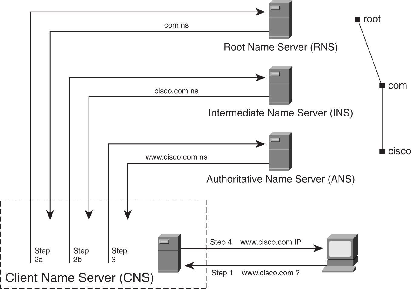
With the introduction of GSS, the DNS resolution process remains the same, except the ANS responsibility has been taken over by the GSS.
##### Using GSS
As the authoritative name server for a domain, GSS will return the IP address of a requested website when it receives requests from the CNS. Unlike the traditional ANS, which is usually a server, GSS formulates its reply based on certain criteria, such as the following:
• Availability of servers
• Proximity of sites
• Load of server
• Source of request
• User-specific preference
As shown in [Figure 9-29](https://learning.oreilly.com/library/view/building-resilient-ip/1587052156/ch09.html#ch09fig29), the DNS resolution process for [www.cisco.com](http://www.cisco.com/) involving a GSS will be as follows:
**1** The client sends a request to the CNS for the IP address of [www.cisco.com](http://www.cisco.com/).
**2** The CNS is redirected to the GSS, because the GSS is the ANS for [cisco.com](http://cisco.com/).
**3** Based on the feedback information from the SLB devices within both the data centers, GSS selects an appropriate site to serve the request (in this case, data center 2).
**4** GSS returns the virtual IP address on the SLB residing in data center 2 to the CNS.
**5** The CNS sends the virtual IP address to the client.
**6** Client sends its request to the SLB residing in data center 2, and the SLB proceeds to handle the client request as described in the section “[Server Load Balancing](https://learning.oreilly.com/library/view/building-resilient-ip/1587052156/ch09.html#ch09sec2lev15).”
**Figure 9-29** _Global Site Selector in Action_
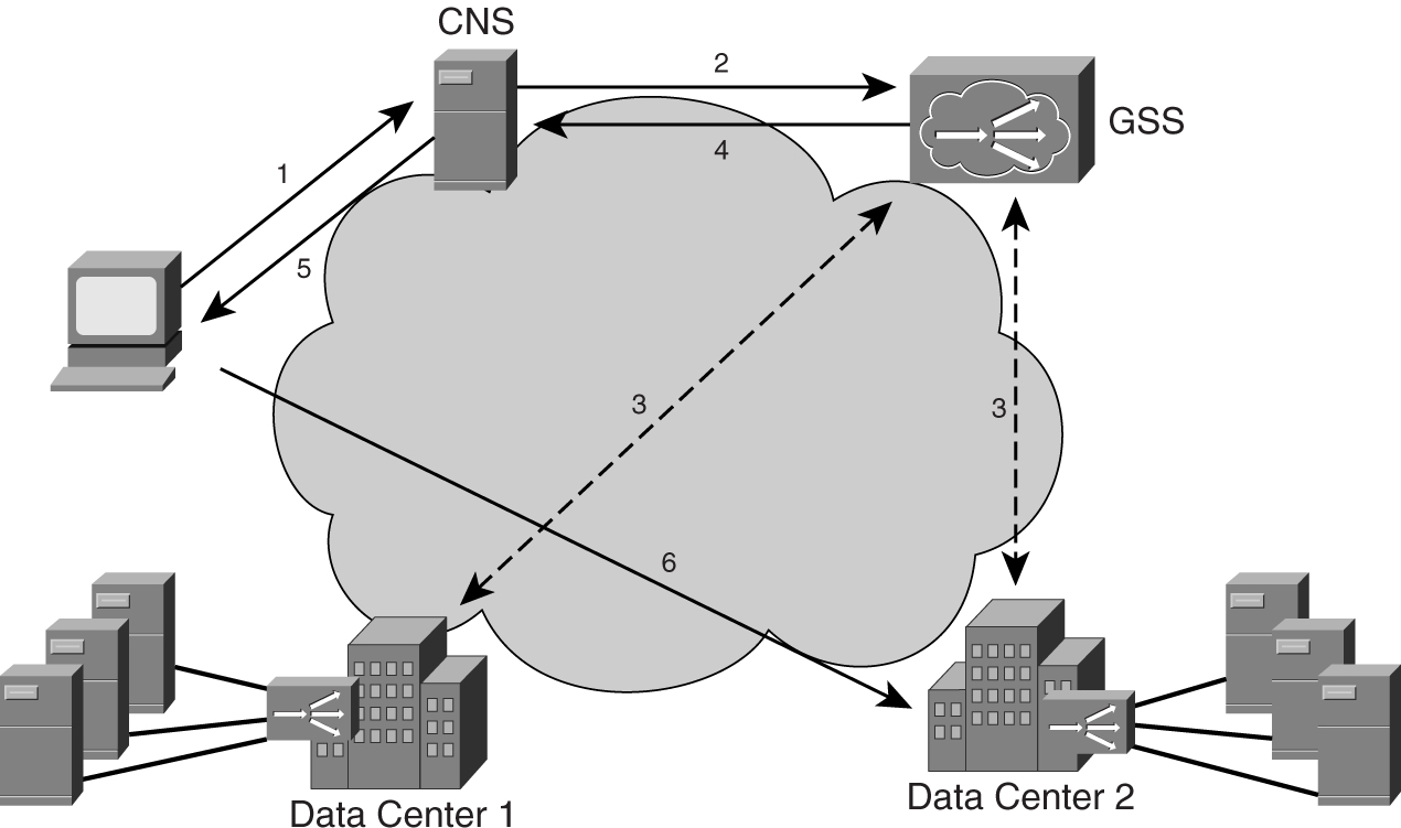
Working hand in hand, the combination of SLB and GSS improves the availability of information. The redundancy is elevated from protecting server failure to protecting data center failure.
#### Web Cache Communication Protocol (WCCP)
Although SLB and GSS ensure the high availability of information, they may not solve some fundamental issues of Internet connectivity. With the proliferation of web traffic, the traditional 80/20 rule of traffic distribution no longer applies. In the past, it was assumed that 80 percent of traffic would stay within a network, whereas only 20 would be outbound traffic. Today, with Internet access, most of the information resides outside of the network. Therefore, network managers must solve the associated problems that arise from this phenomenon:
• **Reduce WAN congestion**—WAN connectivity gets choked with more outbound traffic. In areas such as the Asia Pacific, upgrading WAN connectivity can be costly.
• **Improve user experience**—With most traffic bound for the Internet and limited WAN connectivity, maintaining an acceptable user experience becomes an issue when congestion occurs.
Web caching is one area of server optimization where the network tries to fulfill content requests locally. In doing so, it helps to improve user experience, by accelerating the delivery of content locally, and improves WAN performance by cutting down on repeated requests. The protocol that makes web caching possible is the Web Cache Communication Protocol (WCCP).
[Figure 9-30](https://learning.oreilly.com/library/view/building-resilient-ip/1587052156/ch09.html#ch09fig30) shows the traffic flow with WCCP:
**1** Client sends HTTP request for a particular website.
**2** Request is intercepted by the WCCP running in the router and is redirected to the content engine based on the protocol of the request.
**3** Two options are possible, depending on whether the content is stored locally:
**a** Content engine fulfils the request if it has the content stored locally.
**b** For content that is not stored locally, the content engine sends the request to the actual server for the requested content.
**3** Server sends content to the content engine, and the content engine stores a copy for local storage. Subsequent request will be fulfilled locally.
**4** The content engine sends the content to the client.
**Figure 9-30** _Web Cache Communication Protocol_
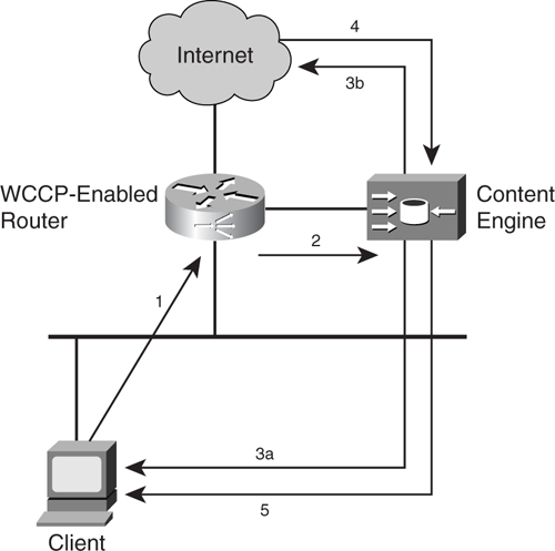
This method of caching is also known as _transparent caching_ because the steps are transparent to the clients. There is no need for the client to have a special configuration in its browser or workstation. In fact, the client does not know that its request has been redirected or that the content engine exists.
Because the working of transparent caching is invisible to users, it has to take care of failure scenarios in an invisible manner, too. Potential problems that might arise include an overloading situation or failure of the cache engine.
A sudden surge in client requests might overload the cache engine; after all, the cache engine can process only a fixed number of transactions per second. In this situation, the cache engine might issue an overload bypass request, in which client requests are forwarded to the real servers. Return traffic from the servers is sent to the client directly, bypassing the cache engine in its return path.
For redundancy purposes, WCCP allows for a group of cache engines to service the redirected request. This group, called a _cache cluster_, can scale up to 32 cache engines. Cache clusters allow the caching capability to scale in a linear manner. With each cache engine supporting a certain numbers of transactions per second, adding extra cache engines increases the overall transaction’s capability of the cache farm.
With WCCP version 1, only a single router services a cluster. When a cache engine is connected to the router, they communicate via UDP port number 2048. The communication between the router and the cache engine minimizes configuration and allows for new cache engines to be added to the cluster without reconfiguration. Within the cluster, the cache engine with the lowest IP address is elected the leader, and it determines how redirection should be redistributed among the caches. Only redirection of HTTP traffic (TCP port 80) is supported by WCCP version 1.
WCCP version 2 improves on the previous version by allowing a group of routers to redirect traffic to a cache cluster. This way, the caching infrastructure is greatly enhanced. WCCP version 2 introduces the concept of a service group; a subset of the cache cluster is mapped to a subset of the router with the same service. WCCP version 2 supports a variety of redirected traffic. Besides HTTP (TCP port 80), it also supports various UDP and TCP traffic, such as FTP, audio, and video applications.
[Example 9-5](https://learning.oreilly.com/library/view/building-resilient-ip/1587052156/ch09.html#ch09ex05) shows a WCCP configuration. In this example, all web traffic arriving at interface fastethernet 2/0/1 will be redirected.
**Example 9-5** _Configuring a Web Cache Communication Protocol_
---
router# configure terminal
router(config)# ip wccp web-cache
router(config)# interface fastethernet 2/0/1
router(config-if)# ip wccp web-cache redirect in
Router(config-if)# exit
---
Just as a cache engine can be deployed to accelerate a client’s request for content, it can be placed in front of web servers to speed up the delivery of content. This way of deploying the cache engine, called _reverse proxy caching_, is an effective way to offload traffic from the servers. Reverse proxy caching improves server capacity and website performance, thus enhancing the overall user experience. With reverse proxy caching, the most popular static web content is cached so that servers need not keep servicing the same request again and again.
The steps are involved in reverse proxy caching, as illustrated in [Figure 9-31](https://learning.oreilly.com/library/view/building-resilient-ip/1587052156/ch09.html#ch09fig31):
**1** Connection from the Internet requests content from the server.
**2** Router with WCCP enabled redirects the request to the content engine.
**3** Depending on whether the content is stored locally, one of the following occurs:
**a** Content engine fulfills the request if it has the content stored locally.
**b** For content that is not stored locally, the content engine sends the request to the actual server for the requested content.
**3** Server sends content to the content engine; content engine stores a copy for local storage. Subsequent request will be fulfilled locally.
**4** Content engine sends the content to the client.
**Figure 9-31** _Reverse Proxy Caching_
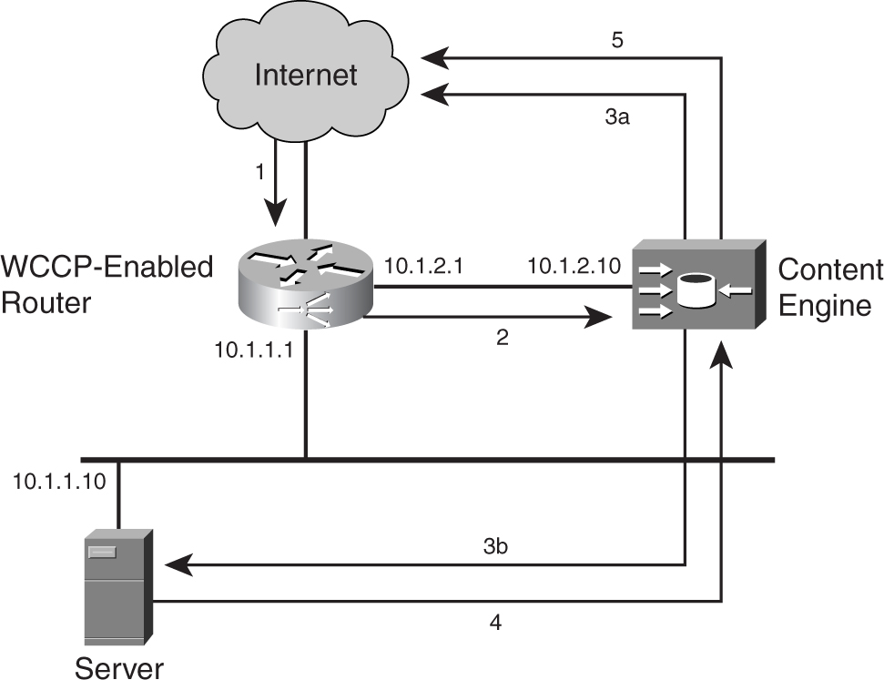
The configuration of the cache engine for the reverse proxy caching function is shown in [Example 9-6](https://learning.oreilly.com/library/view/building-resilient-ip/1587052156/ch09.html#ch09ex06).
**Example 9-6** _Configuring Reverse Proxy Caching on a Cache Engine_
---
Cacheengine#config terminal
Cacheengine#(config)#wccp version 2
Cacheengine#(config)#wccp router-list 1 10.1.2.1
Cacheengine#(config)#wccp 99 reverse-proxy router-list-num 1
---
The configuration of the router for the support of reverse proxy caching is shown in [Example 9-7](https://learning.oreilly.com/library/view/building-resilient-ip/1587052156/ch09.html#ch09ex07).
**Example 9-7** _Configuring Reverse Proxy Caching on a Router_
---
Router#config terminal
Router(config)#ip wccp 99
Router(config)#interface s0/0
Router(config-if)#ip wccp 99 redirect in
---
WCCP is an important component of the overall server farm architecture. When you integrate WCCP into the network, it can either optimize the WAN usage or it can improve the performance of the server farm. One point to note, however, is that WCCP is CPU intensive and, depending on the configuration, may have different impact on the performance of the router.
### Integrated Service Modules
Up to this point, topics such as Layer 2 security, Layer 3 security, server load balancing, and even web caching have been discussed as individual topics. It might seem that these features are implemented via different hardware, implementations that might pose a problem within the data center. As it is, real estate in the data center is precious, and not many network managers have the luxury of working with ample rack space. This is where the concept of integrated service modules of the Cisco Catalyst 6500 and the 7600 family comes in.
The availability of the various service modules of the Catalyst 6500 family changes its role within the data center. More than just a switch with Layer 3 features, the inclusion of these service modules turned the Catalyst 6500 family into an IP service platform within the data center.
Many service modules are available on the Catalyst 6500 family, and the following are relevant to the data center environment:
• **Firewall Service Module (FWSM)**—Used to provide a high-performance firewall function at 5-Gbps throughput, 100,000 connections per second, and 1 million concurrent connections.
• **Content Switching Module (CSM)**—Used to provide load balancing of firewalls, web servers, caches, and other network devices.
• **SSL Service Module (SSM)**—Provides accelerations and increases security of web applications.
• **Anomaly Detection and Mitigation Modules**—Detects DoS attacks and blocks malicious traffic without affecting normal traffic.
• **Network Analysis Module (NAM)**—Provides visibility into the traffic flow within the data center network. The monitoring functions can help you fight DoS attacks.
The use of service modules is a relatively new concept to many network managers. Besides saving rack space and power, their benefit is in the way they work in an integrated manner, as part of the data center architecture. When used in combination, they transform the server farm into a highly scalable and secure infrastructure. However, depending on the logical IP network design, care should be taken with respect to routing and performance issues. For example, you might end up with the FWSM performing a basic routing function, when it can be done by the MSFC within the same chassis. Another example is that if you place the FWSM into a bridge mode, you might lose features such as NAT.
Because many different service modules are available within the Catalyst 6500 and Cisco 7600 families of products, you have many possibilities of deploying them. However, this also means more planning needs to be done it terms of usage. A good source of information about how to leverage the powerful combination of the service modules can be found in _Data Center Fundamentals_, by Mauricio Arregoces and Maurizio Portolani (Cisco Press, 2004).
### Summary
Maintaining high availability for the data center module requires multidisciplinary knowledge such as construction, networking, server, security, and operation experience.
Constructing the data center module requires network designers and managers to have multifaceted knowledge. Professionals who are good in this area usually possess a wide array of technical expertise that spans various disciplines: construction, networking, server, storage, security, and operation experience. This chapter presented the overall challenge of building a data center module.
The data center module is closely linked to operational issues, such as fault detection and overall management of the infrastructure, which you learn about in [Chapter 10](https://learning.oreilly.com/library/view/building-resilient-ip/1587052156/ch10.html#ch10), “[Beyond Implementation](https://learning.oreilly.com/library/view/building-resilient-ip/1587052156/ch10.html#ch10).”
table of contents
search
Settings
[Chapter 8. WAN Module](https://learning.oreilly.com/library/view/building-resilient-ip/1587052156/ch08.html)
Chapter 9. Data Center Module
queue
Building Resilient IP Networks
[Chapter 10. Beyond Implemention: Network Managment
](https://learning.oreilly.com/library/view/building-resilient-ip/1587052156/ch10.html)