[Skip to Content](https://learning.oreilly.com/library/view/qos-for-fixed/9781119470502/c02.xhtml#main)
[](https://learning.oreilly.com/home/)
- Explore Skills
- Start Learning
- Featured
[Answers](https://learning.oreilly.com/answers2/)
Search for books, courses, events, and more
# 2
Internet QoS
The Internet was created to provide only best‐effort services, which means that every connection is admitted into the network and every packet is transferred from source to destination with the best effort by the network, and without any guarantees regarding quality of service.
However, from the beginning the Internet designers allocated for QoS support even in the fundamental Internet Protocol in both versions, IPv4 (IP version 4, which is also simply referred to as IP) and IPv6 (IP version 6). That was done because it was known that different type of media such as audio, video, and data, have different requirements on certain quality metrics (bitrate in downlink and uplink, delay, losses, etc.). Those protocols are standardized by the IETF, the main standardization body for Internet technologies (i.e. it includes protocols and architectures from the network protocol layer up to the application layer, which are used in hosts and nodes attached to the Internet network).
Since the beginning of the twenty‐first century the whole telecommunication world has been transiting to the Internet as a single networking platform for all telecommunication services, including native Internet services (e.g. Web, email) and traditional telecommunication services (e.g. telephony, television). That makes for different QoS techniques which are standardized for legacy telecommunication networks (e.g. PSTNs) to be implemented in a certain manner in IP networks (here, an IP network is based on the Internet networking principles and has IP protocol implemented in all hosts and nodes in the given network). Also, there were certain QoS solutions specifically standardized for the Internet by the IETF, and such solutions have further influenced QoS mechanisms in the telecommunication/Information and Communication Technologies (ICTs) world based on Internet technology protocols.
It has been said that the long‐term goal of networking is to design a network that has the flexibility and low cost of the Internet and at the same time can provide the end‐to‐end QoS guarantees of the telephone network. However, that is not a simple process when there are many services with different quality requirements over a single network.
## 2.1 Overview of Internet Technology Protocols
Internet technology protocols are placed in the upper layers of the protocol layering model, covering the range from the network layer (layer 3) up to the application layer (layer 7). However, the main protocols are those implemented at the network layer and the transport layer (layer 4). The main protocol is the IP, which currently is standardized in two versions, IPv4 [[1]](https://learning.oreilly.com/library/view/qos-for-fixed/9781119470502/c02.xhtml#c02-bib-0001) and IPv6 [[2]](https://learning.oreilly.com/library/view/qos-for-fixed/9781119470502/c02.xhtml#c02-bib-0002). The main transport layer protocols are the user datagram protocol [[3]](https://learning.oreilly.com/library/view/qos-for-fixed/9781119470502/c02.xhtml#c02-bib-0003) and the transmission control protocol [[4]](https://learning.oreilly.com/library/view/qos-for-fixed/9781119470502/c02.xhtml#c02-bib-0004). However, there are others that may exist in layer 4, such as SCTP (stream control transmission protocol) [[5]](https://learning.oreilly.com/library/view/qos-for-fixed/9781119470502/c02.xhtml#c02-bib-0005) and DCCP (datagram congestion control protocol) [[6]](https://learning.oreilly.com/library/view/qos-for-fixed/9781119470502/c02.xhtml#c02-bib-0006).
### 2.1.1 Internet Network Layer Protocols: IPv4 and IPv6
IP is the main communication protocol in the IP stack. It is positioned on the network protocol layer (layer 3) and provides functions for transmission of datagrams (i.e. blocks of data) over interconnected systems of packet‐switched networks from any source to any destination.
IP is a connectionless protocol because it does not require a connection to be established between the source host and the destination host prior to the datagrams' transmission. When the IP first appeared (at the beginning of the 1980s) it was completely different from the traditional telecommunication approach in PSTNs where connections were established (prior to the transfer, such as voice transfer) by using signaling between the two end devices and the network.
Internet datagrams are also called IP packets, so the terms are used interchangeably throughout this book. In general, a datagram is a variable length packet consisting of two parts: IP header and data (in the payload of the packet).
The IP has exactly two versions (not more, not less):
- IPv4, standardized in 1981 by the IETF [[1]](https://learning.oreilly.com/library/view/qos-for-fixed/9781119470502/c02.xhtml#c02-bib-0001);
- IPv6, standardized in 1998 by the IETF [[2]](https://learning.oreilly.com/library/view/qos-for-fixed/9781119470502/c02.xhtml#c02-bib-0002).
The IPv4 and IPv6 packet headers are shown in Figure [2.1](https://learning.oreilly.com/library/view/qos-for-fixed/9781119470502/c02.xhtml#c02-fig-0001). The main difference is that IPv6 addresses are four times longer (128 bits) than IPv4 addresses (which have a length of 32 bits). The main driver for introduction of IPv6 was in fact IPv4 address space exhaustion, which started to become evident with the exponential growth of the Internet in the 1990s. However, IPv6 does offer several other improvements to the IPv4 header, such as reducing some fields which refer to packet IP packet fragmentation (that is fragmentation of a single IP packet into multiple fragment packets at a certain point in the network, such as a router, and then doing the reverse process at some point in the downstream direction) which has proven to be inefficient for practical use (e.g. if some of the routers on the way do not handle the fragmentation of the IP packets well, the IP communication will suffer interruptions), hence these fields are omitted in the newer IPv6 header. However, due to longer IP addresses, IPv6 has a header that is at least two times longer (a minimum of 40 bytes) than its predecessor IPv4 (a minimum of 20 bytes), which influences certain traffic types such as voice which have low‐length payload (due to lower traffic intensity of the voice). Another difference is the Flow Label field introduced in IPv6 with the intention of labeling individual IP flows on layer 3 (network layer), which may be important for QoS provisioning per flow. Nevertheless, the Internet was created for IPv4 networks and QoS solutions targeting IPv4 networks, so one may expect such mechanisms (e.g. for traffic management) to continue to be used for IPv6 networks, which limits the possibilities of end‐to‐end use of the Flow Label.
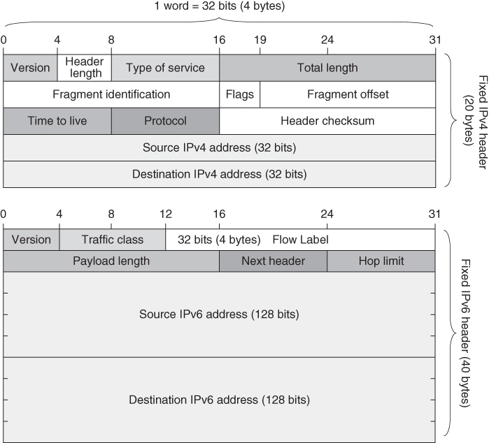
[Figure 2.1](https://learning.oreilly.com/library/view/qos-for-fixed/9781119470502/c02.xhtml#R_c02-fig-0001) Comparison of IPv4 and IPv 6packet headers.
Regarding the QoS on the network layer, the most important field in IP headers is Type of Service (ToS) in IPv4 as well as DSCP (Differentiated Services Code Point) in IPv6. Both fields have the same length (1 byte, i.e. 1 octet of bits) and can be used for traffic differentiation on the network layer, for marking packets (with this field in the IP headers) which belong to the same aggregate traffic type (also called a traffic class or QoS class), such as voice, TV, various data, VPN (virtual private network), etc.
IP packets travel across different IP‐based networks which are using different underlying transport technologies (this refers to network interfaces defined with layers 1 and 2 of the protocol stack). For example, the most used local area network (LAN) for Internet access in home and business environments is Ethernet (IEEE 802.3 standard) and WiFi (IEEE 802.11 family of standards) as unified wireless LAN (WLAN). Both main Internet access standards, Ethernet and WiFi, are standardized by the Institute of Electrical and Electronics Engineers (IEEE) only on layer 1 and layer 2 (i.e. physical layer and data‐link layer, respectively), while on layer 3 it is expected to carry primarily IP packets, that is, to have IP on the protocol layer 3. So, from inception (Ethernet appeared in the 1980s and WiFi at the end of the 1990s) they were built to carry Internet traffic in the local area networks. Of course, one should note that these access networks are typically connected via other broadband access technologies (fixed or mobile) to the core networks of the network providers. However, due to their influence globally on the Internet network infrastructures, the size limit in their layer 2 payloads (that is Medium access control (MAC) frame payload), which is approximately 1500 bytes, in fact defines the maximum size of IP packets (either IPv4 or IPv6) which travel across the Internet, regardless of the type of traffic they carry (voice, video, or some other data).
IPs as well as all other Internet technologies are being standardized by the IETF ([www.ietf.org](http://www.ietf.org/)) in a form of RFCs (request for comments). Not all RFCs are Internet standards, some are informational only. Also, there are Internet technologies which are proprietary and not standardized (e.g. developed by certain vendors). Such proprietary technologies are typically developed on the application layer (e.g. various OTT applications in the public Internet), although there are also proprietary versions of some networking protocols, such as proprietary TCP versions and proprietary routing protocols.
### 2.1.2 Main Internet Transport Layer Protocols: TCP and UDP
Internet networking is based on network layer protocol (IP) and transport layer protocols (TCP, UDP). Networking protocols are implemented in the operating system (OS) of the hosts or network nodes and they are connected with the application using the abstraction called “socket,” as an endpoint of a communication call/session in IP environments.
What is a “socket”? It is an abstraction which connects the IP address of the network interface (used for access to the IP network), port numbers, and type of transport protocol being used in the communication. From an application point of view, it hides from the application all Internet networking protocols below (e.g. TCP/IP, UDP/IP), which are built into the OS of the host or the network node (e.g. router, gateway). The socket interface for the application is defined with an application programming interface (API), which is specific to the OS of the given host or network node. Therefore there is required development of a given application for a given OS (different API exists in Windows, Linux, Android, iOS, etc.).
From the network point of view, the socket is the endpoint of a given Internet connection. So, if a typical connection includes two end parties (e.g. two Internet hosts), then the connection (a call, a session) is established between two open sockets at the two end hosts. If one of the sockets closes, it means that the given connection is also considered as closed. So, to maintain a given connection means to keep open the sockets between the two ends. That refers to both fixed and mobile Internet access. However, it is more complex to keep the socket open during a connection for a moving host which typically changes a point of attachment to the network (while it is moving), and hence it may change the IP network to which it is attached, which means that the IP address must change in such a case. But if any of the parameters (IP address, port number, transport protocol type) which define a given socket change, it means that a new socket should be opened and the previous one closed. That results in closing (i.e. dropping) the connection and opening a new one (that is, a new connection with a new socket). However, in such a case there is no mobility because mobility means maintaining the same connection of mobile hosts regardless of their movement. Due to such mobility problems in IP network environments, there are certain solutions on the network layer for Internet hosts, which include standardized protocols such as Mobile IP (for IPv4 mobile networks) [[7]](https://learning.oreilly.com/library/view/qos-for-fixed/9781119470502/c02.xhtml#c02-bib-0007) and Mobile IPv6 (for IPv6 mobile networks) [[8]](https://learning.oreilly.com/library/view/qos-for-fixed/9781119470502/c02.xhtml#c02-bib-0008). But in mobile networks (until and including 4G) the mobility is typically handled on the data‐link layer (below the IP layer), which hides the mobility from the network layer up and hence eliminates potential problems that may arise from the IP addressing principles (which were initially created for fixed hosts only).
After defining the sockets that bind the IP (on the network layer) and the transport layer protocols, let's see which are the main transport protocols and their main principles influencing QoS. The main transport protocols are:
- UDP, standardized with RFC 798 in 1980 [[3]](https://learning.oreilly.com/library/view/qos-for-fixed/9781119470502/c02.xhtml#c02-bib-0003);
- TCP, initially standardized in 1981 [[4]](https://learning.oreilly.com/library/view/qos-for-fixed/9781119470502/c02.xhtml#c02-bib-0004) but later updated with congestion control mechanisms in the 1990s [[9]](https://learning.oreilly.com/library/view/qos-for-fixed/9781119470502/c02.xhtml#c02-bib-0009). TCP mechanisms are continuously being updated [[10]](https://learning.oreilly.com/library/view/qos-for-fixed/9781119470502/c02.xhtml#c02-bib-0010) simply because there is no single best congestion control mechanism for all times.
UDP/IP is typically used for real‐time data (e.g. VoIP, IPTV) and certain control traffic (e.g. the domain name system (DNS) uses UDP/IP). In practice, UDP adds only source and destination port numbers (Figure [2.2](https://learning.oreilly.com/library/view/qos-for-fixed/9781119470502/c02.xhtml#c02-fig-0002)), which are being used by sockets opened on both ends of the communication connection. The port numbers identify the application using the given transport protocol layer (UDP in this case). All well‐known protocol numbers are defined by the IANA, the non‐governmental body governing the Internet on a global scale. So, UDP has no particular direct function regarding QoS. However, thanks to its simplicity (no guarantees for datagram delivery end‐to‐end), UDP provides the lowest end‐to‐end delay (because there are no retransmissions of lost packets, which requires additional time and hence adds delay), which is useful for some services that are delay sensitive (voice is the most typical example of a service that uses UDP/IP). Yet since there are no guarantees or feedback control (from the receiving host to the sending host), typically the control is implemented into the application (e.g. DNS) or another protocol used over UDP, such as RTP (real‐time transport protocol) [[11]](https://learning.oreilly.com/library/view/qos-for-fixed/9781119470502/c02.xhtml#c02-bib-0011). RTP provides synchronization of multiple media streams (e.g. video and accompanied audio streams) as well as control messages exchange in both directions between sender and recipient by using its counterpart protocol called RTCP (real‐time transport control protocol). For example, voice communication over IP uses voice application over RTP/UDP/IP protocol stack, although it is possible for RTP‐like functionalities to be implemented in a certain manner in the VoIP application, something that is typical for OTT voice services.
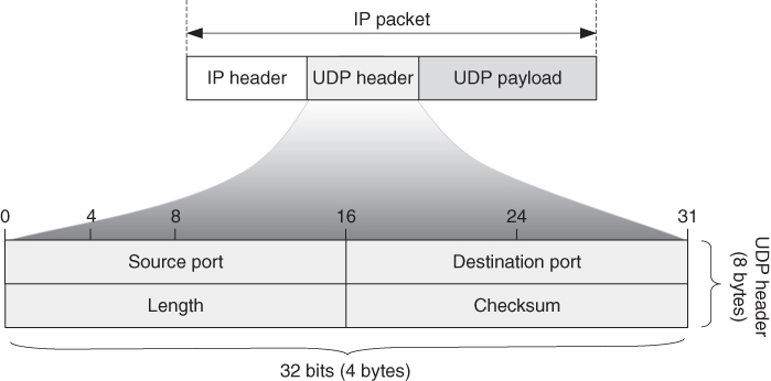
[Figure 2.2](https://learning.oreilly.com/library/view/qos-for-fixed/9781119470502/c02.xhtml#R_c02-fig-0002) User datagram protocol (UDP).
Unlike UDP, which is very light (regarding implementation and resource consumption at the host) and has no particular function except providing port numbers (which is good for some real‐time applications), TCP can be considered as one of the most important Internet technology protocols. Why? Because the initial concept of Internet networking for end‐to‐end QoS support is implemented with TCP at the end hosts. While in traditional telecommunication networks, the PSTNs, the intelligence was located inside the network and hosts were very simple devices (traditional telephones), in the Internet the intelligence for dealing with end‐to‐end QoS (e.g. congestion control) is implemented at end hosts (which are typically computers such as personal computers, smartphones, or other type of devices with hardware and software on them) via TCP. But TCP has also evolved with the Internet. During the ARPANET era in the 1970s, TCP functionalities were in fact implemented in one protocol together with network functionalities (which are now part of IP), called a network control program (NCP), as a single protocol implemented between the applications on the top and the network interface at the bottom of the hosts. However, with the standardization of IP and TCP in 1981, the NCP split into two main protocols: IP as a network protocol and transport protocols (TCP and UDP) over it. This was first implemented in the BSD (Berkeley Software Distribution) Unix OS in the 1980s and implemented in all Internet hosts (several hundred of them) on January 1, 1983, known as Internet flag day. Because of the low number of hosts connected to the Internet at the time, it was possible to change the OS in all of them in a short period of time. However, is another flag day possible? Well, when the Internet has billions and tens of billions of hosts (including things attached to the Internet, besides humans with their devices), it becomes almost impossible to implement such change in all hosts at the same time (nowadays the changes must be gradual and backward compatible).
The TCP standardized in 1981 had no congestion control mechanisms. When the Internet began to grow and expand outside the research community with the appearance of NSFNET (National Science Foundation Network) in 1985, which made it possible for companies to connect to the network, congestion started to appear more frequently. The initial solution was standardization of congestion control mechanisms for TCP [[9](https://learning.oreilly.com/library/view/qos-for-fixed/9781119470502/c02.xhtml#c02-bib-0009),[10](https://learning.oreilly.com/library/view/qos-for-fixed/9781119470502/c02.xhtml#c02-bib-0010)]. Such mechanisms include Slow Start, Congestion Avoidance, Fast Retransmission, and Fast Recovery. In fact, TCP uses acknowledgements sent by the TCP receiver to the TCP sender to acknowledge the last received TCP segment in sequence (with no lost or reordered segments before). TCP has a congestion window (CW), which defines the number of TCP segments that can be transmitted (of course, the TCP segment is placed into a payload of an IP packet) back‐to‐back, that is, without waiting for acknowledgments to arrive. Each non‐duplicate acknowledgment increases the number of segments received and hence pushes the CW, so the CW is in fact a sliding window. It is also a dynamic window, which means that its size in almost all TCP versions is never a constant value over time, so it either increases its size (with certain triggers for that such as received positive acknowledgments for successful receipt of the TCP segments by the other end) or decreases its size (again, with certain triggers such as packet losses or timeouts). Bigger CW gives higher bitrates, that is, achievable bitrates for a given TCP connection are proportional to the CW size. Let us explain this through an example.
If a TCP segment is carried in 1500 bytes long IP packets (typical size for Web or video traffic), then (as an example) 10 Gbit/s for a given TCP connection for a given RTT (round trip time) between the TCP sender and the TCP receiver can be reached with a CW of size:
(2.1)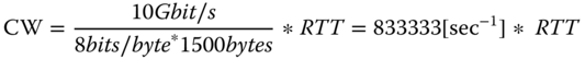
For RTT = 100 ms = 0.1 s, the required CW size of TCP to reach the maximum bitrate of 10 Gbit/s will be CW = 83 333, while the CW size required in the case of RTT = 10 ms will be CW = 8333. So, the CW size depends upon the capacity of the bottleneck link between the two ends (which communicate by using TCP/IP) and the RTT. One may note that bitrate of the application that is using TCP/IP is directly related to the CW size of the TCP in use. Hence, bigger CW is needed to reach higher speeds and vice versa.
However, the main target of TCP is not only to reach maximum capacity (i.e. bitrate) available end‐to‐end but also to provide fairness based on its congestion avoidance mechanism.
The following are the main TCP congestion control mechanisms (Figure [2.3](https://learning.oreilly.com/library/view/qos-for-fixed/9781119470502/c02.xhtml#c02-fig-0003)):
- Slow start provides an exponential increase in the CW size with the aim of reaching the capacity of the bottleneck for the given TCP connection sooner (in the default version, in slow start CW is doubled for each RTT interval). Usually, slow start begins with a CW size equal to one segment, although there are TCP versions which provide slow starts with higher initial values (two TCP segments or more).
- _Congestion avoidance_. It provides linear increase of the CW size with the aim of postponing congestion (which results in packet losses).
- _Fast retransmission_. After a lost TCP segment, TCP reacts after receiving a certain number of acknowledgments for TCP segments successfully transmitted after the lost one (e.g. three duplicated acknowledgments) and reacts by reducing the size of CW (e.g. to half).
- _Fast recovery_. This mechanism provides the possibility for TCP to stay in the congestion avoidance phase after packet loss, thus avoiding going into slow start phase and avoiding significant disruption of the bitrate of the given connection. However, multiple TCP losses within the CW may lead to expiration of TCP timeouts (e.g. maximum time for waiting for acknowledgements), which may result in transition to slow start.
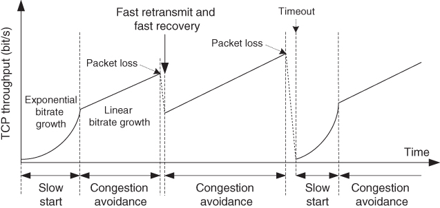
[Figure 2.3](https://learning.oreilly.com/library/view/qos-for-fixed/9781119470502/c02.xhtml#R_c02-fig-0003) TCP congestion control.
Different TCP versions may implement the above basic congestion control mechanisms partially, modify them in certain aspects (e.g. regarding the phases and their trigger), or combine TCP and UDP characteristics to achieve reliable and low‐delay transfer (e.g. for services such as video streaming or IPTV).
TCP payload contains data from application protocols that use TCP (e.g. the Web, i.e. Hypertext Transfer Protocol (HTTP)), email protocols, File Transfer Protocol (FTP)). TCP is a client‐server protocol which establishes a connection between two end hosts prior to the data transfer. For connection establishment it uses a three‐way handshake. “Fake” TCP connection establishment requests are the basis for denial of service (DoS) attacks, which affect the availability of the application or service provided via TCP.
### 2.1.3 Dynamic Host Configuration Protocol – DHCP
The Dynamic Host Configuration Protocol (DHCP) is a standardized protocol for dynamic provision of network configuration parameters to Internet hosts in a given IP network. DHCP exists in every network, including telecom internal networks, and enterprise or home networks. DHCP has prolonged the life of IP version 4 (the initial IP) [[12]](https://learning.oreilly.com/library/view/qos-for-fixed/9781119470502/c02.xhtml#c02-bib-0012), providing the possibility to serve more users with a limited pool of public IP addresses. However, DHCP has fundamental importance for the global Internet and for the telecommunication world based on the Internet technologies for providing a plug‐and‐play approach for access to the Internet. How? Well, besides the dynamically allocated IP address, the DHCP sets other networking information, of which the most important are the IP addresses of the DNS servers because without access to a DNS server a given host cannot resolve domain names into IP addresses, which is necessary for Internet‐based communication. Therefore DHCP is also standardized for dynamic assignment of IPv6 addresses, called DHCPv6 [[13]](https://learning.oreilly.com/library/view/qos-for-fixed/9781119470502/c02.xhtml#c02-bib-0013).
From the QoS point of view, proper functioning of the DHCP server in the IP network to which a given host is attached is crucial in order for a host to obtain an IP address on its network interface in a plug‐and‐play manner and to have Internet connectivity.
### 2.1.4 Domain Name System – DNS
While in traditional telephone networks the main naming and addressing space was (and it still is) the telephone numbering space, standardized and governed on a global scale by the ITU (defined with ITU‐T E.164 telecommunication numbering plan [[14]](https://learning.oreilly.com/library/view/qos-for-fixed/9781119470502/c02.xhtml#c02-bib-0014)), on the Internet there are exactly two name spaces, which are governed on a global scale by ICANN and its department IANA. These two name spaces are:
- IP addresses, including:
- IPv4 addresses, e.g. 194.149.144.1 (typically given in decimal‐dot notation, with a length of 32 bits)
- IPv6 addresses, e.g. 2001:0000:0000:0000:0008:0800:200C:417A (typically given in a hexadecimal notation, with a length of 128 bits);
- domain names [[15]](https://learning.oreilly.com/library/view/qos-for-fixed/9781119470502/c02.xhtml#c02-bib-0015), e.g. “[www.itu.int](http://www.itu.int/),” “[www.ietf.org](http://www.ietf.org/).”
DNS was created to provide a means for using names (domains) instead of IP addresses to access certain machines on the network as people more easily use names than long numbers. However, machines communicate over the Internet only via IP addresses, so the domain name must be resolved to an IP address (which corresponds to the given domain name according to the DNS system records). For that purpose, DNS is a distributed hierarchically‐based system which translates a domain name to an IP address associated with that domain.
DNS is a fundamental Internet technology which provides translation between the two name spaces on the Internet. However, it is characterized by two conceptually independent aspects:
- The first is the definition of names and rules for delegation of authority for the names.
- The second is specification of a distributed computer system which will provide efficient mapping of domain names to IP addresses and vice versa.
The domain name space is defined as a tree structure, with the root on the top. Each domain name consists of a sequence of labels, which are separated with dots, and each label corresponds to a separate node in the domain tree. For example, in the domain name “[www.itu.int](http://www.itu.int/)” one will observe that it consists of three labels divided by dots. The label on the right side is always higher in the name hierarchy. So, in the given example the top‐level domain is the domain “int.”
Regarding QoS, DNS availability is very important for Internet services' accessibility. In fact, besides a physical connection to the network, to have availability of Internet access service (as a whole) requires an IP address (which is allocated dynamically with DHCP) and at least one available DNS server (and its IP address). Typically, IP addresses of two or three DNS servers are set up in each host connected to the Internet, due to the importance of the DNS functionalities. Each host has a DNS client built into it, which contacts the DNS server (from a defined list). In order to have lower RTT for DNS resolution (e.g. resolution of a domain name into an IP address), it is important to have DNS servers closer to the clients (e.g. in the same IP network, where possible), although a DNS client can send a request to any available DNS server on the Internet. However, not all DNS servers have records for all possible domain names. If a certain record is not available, the contacted DNS server sends a request to another DNS server either iteratively or recursively (to different DNS servers, according to obtained responses). If there is no possible DNS communication, the user can still connect to a server or a peer host by specifying directly the IP address of the destination host. However, that is not feasible in most cases (e.g. the requesting user usually does not know the destination IP address, and it is not convenient to include IPv4 and especially longer IPv6 addresses).
DNS is implemented on the application layer (regarding the protocol stack) and initially it used UDP (as a transport protocol) due to its lower delay. However, with the deployment of high‐speed Internet links and access around the globe, as well as with the higher processing power in all hosts (which doubles every 1.5–2 years according to Moore's law), there is also a standardized approach for DNS communication by using TCP as transport layer protocol [[16]](https://learning.oreilly.com/library/view/qos-for-fixed/9781119470502/c02.xhtml#c02-bib-0016).
Overall, proper functioning of DNS as well as lowest possible DNS resolution times are key performance parameters for Internet QoS because they directly refer to Internet service availability and accessibility.
### 2.1.5 Internet Fundamental Applications
#### 2.1.5.1 Web Technology
The World Wide Web (WWW) is a global system started in 1989 by Tim Berners Lee and completed with the development of its main standards during the 1990s. The Web (i.e. WWW) is made up of a large number of documents called web pages, each of which is a hypermedia document. “Hyper” means that it contains links to other websites and “media” means that it can contain other objects besides text (pictures, videos, various files, etc.).
The Web is based on the client‐server principle. The main protocol for Web end‐to‐end communication, for access to web pages, is called HTTP. It is based on client‐server TCP/IP protocol model, where:
- Web servers (i.e. HTTP servers) listen on the well‐known TCP port 80;
- Web application on the users' side is called a browser (e.g. Chrome, Firefox, Opera), which has an HTTP client built into it.
So, HTTP is only a communication protocol for Web traffic. The presentation of Web content is done with other tools [[17]](https://learning.oreilly.com/library/view/qos-for-fixed/9781119470502/c02.xhtml#c02-bib-0017), and the most known markup language for creating Web pages is Hypertext Markup Language (HTML).
HTTP was initially standardized with HTTP/1.0 version, which uses a new HTTP connection for each object transfer (non‐persistent mode), where an object can be the text, a picture, etc. However, the widely spread standard over the years was HTTP/1.1, in which one HTTP connection is used for transfer of multiple objects between a client and a server (called persistent mode, or pipelining). It was standardized with RFC 2616 in 1999 [[18]](https://learning.oreilly.com/library/view/qos-for-fixed/9781119470502/c02.xhtml#c02-bib-0018). After more than 15 years of HTTP 1.1 the IETF published HTTP version 2 (HTTP/2) in 2015, standardized with RFC 7540 [[19]](https://learning.oreilly.com/library/view/qos-for-fixed/9781119470502/c02.xhtml#c02-bib-0019).
HTTP/2 addresses several issues that were considered to be disadvantages in HTTP/1.0 and HTTP/1.1 regarding performance of the HTTP connection and Web traffic in general. HTTP/2 defines an optimized mapping of HTTP semantics to an underlying TCP connection. Also, it allows interleaving of request and response messages on the same connection and uses an efficient coding for HTTP header fields. Further, HTTP2 provides the possibility for prioritization of HTTP requests (from HTTP clients, i.e. Web browsers) by allowing more important requests to complete more quickly, which should result in improved performance of Web‐based applications.
#### 2.1.5.2 File Transfer Protocol (FTP)
FTP is an application for copying files from one machine (i.e. host) to another. It was one of the first important application‐layer protocols on the Internet (the first file transfer mechanisms were proposed in 1971 with RFC 114) [[17]](https://learning.oreilly.com/library/view/qos-for-fixed/9781119470502/c02.xhtml#c02-bib-0017).
It is also a client‐server protocol that uses TCP/IP protocol stack. It consumes more resources on the computer than HTTP because FTP requires two processes to be established for file transfer (e.g. file upload or download), a control process (e.g. for user authentication, file administration), and data process (for file transfer). Therefore, it was rarely used after the global spread of HTTP and WWW, which are also used for file upload and download (among other possibilities) and hence make FTP redundant.
Nevertheless, even in the second decade of the twenty‐first century, FTP as a protocol is still used for Internet connection measurements (e.g. bitrate measurements in downlink or uplink).
#### 2.1.5.3 Email Protocols
Email communication is done with standardized IETF protocols [[17]](https://learning.oreilly.com/library/view/qos-for-fixed/9781119470502/c02.xhtml#c02-bib-0017). The main email protocol is SMTP (Simple Mail Transfer Protocol), which is used for sending email from a standalone mail client (Thunderbird, Outlook, etc.) to a mail server and for communication between email servers (e.g. for sending an email from the sending email server to the destination email server, of course after resolving the domain name of that email server via DNS).
For access to the email messages received in the mailbox of the email server, there are standardized access email protocols, which include POP3 (Post Office Protocol version 3) and IMAP4 (Internet Message Access Protocol version 4). Popularization of free email accounts since the 2000s also increased the portion of Web‐based access to email. In such cases the protocol used for access to email is HTTP.
## 2.2 Fundamental Internet Network Architectures
### 2.2.1 Client‐Server Internet Networking
Most of the Internet applications use client‐server communication, which means that there are two types of entities (e.g. hosts, network nodes) in each such communication:
- _Client_ (_e.g. a Web browser_). It sends requests to the server.
- _Server_ (_e.g. Web server_). It sends responses to the client's requests.
The principle of the client‐server communication is such that clients are the entities which request certain information or action from the server. The server is not intended to initiate any action by the client. This is native Internet network architecture, where clients are simpler machines which in average have lower processing power and lower memory capacity than servers because servers must handle multiple requests from multiple clients in parallel. When there are many expected requests from many clients, a single server cannot serve them all, so in such cases multiple servers are serving the clients for a given (same) application or service. The servers can be centralized into a single data center or distributed among several geographically dispersed data centers (e.g. content distribution network (CDN) [[17]](https://learning.oreilly.com/library/view/qos-for-fixed/9781119470502/c02.xhtml#c02-bib-0017)). For example, global OTT service providers have many data centers, which are situated as close as possible to the end‐users in a given region because besides balancing of the servers' load, another important parameter for client‐server communication is the delay in receiving a response from a server for a given client request (also referred to as RTT).
Overall, client‐server architectures are Internet native and fundamental; however, they are not symmetric regarding client and server functionalities and their roles. Both main types of transport protocols (TCP, UDP) as well as others (SCTP, DCCP) are also based on the client‐server principles. The transport protocol on the side of the client application acts as a client (e.g. TCP client, UDP client) and the transport protocol on the side of the server acts as a server (e.g. TCP server, UDP server). Each protocol communication is peer‐to‐peer (P2P), which means that a given protocol (e.g. application, transport protocol) must communicate with exactly the same protocol on the other side of the connection (i.e. the same application protocol and the same transport protocol, respectively).
### 2.2.2 Peer‐to‐Peer Internet Networking
P2P networking is based on network architectures in which each host (computer, smartphone, etc.) or network node (e.g. router) has similar capabilities and functionalities as other peers.
P2P applications for residential users appeared by the end of 1990s. One of the first globally known P2P architectures (besides those used in research) was Napster, which was created and used for sharing of music files (mp3) around the year 2000. It was followed by other file‐sharing systems (e.g. Gnutella, Kazaa, eDonkey, BitTorrent).
All conversational communications over IP networks, such as VoIP or video telephony over IP, are based on P2P communication because in such a case both end‐hosts have similar capabilities and functionalities. So, QoS‐enabled VoIP as a replacement of PSTN (implemented by telecom operators) is in fact implemented with P2P architectures for transfer of voice data.
### 2.2.3 Basic Internet Network Architectures
Basic Internet architecture consists of interconnected IP networks. In each such IP network, every Internet host and router must have implemented the IP on the network layer (in the OSs).
According to the network size (number of hosts as well as distance between the hosts), terrestrial IP networks are typically classified into the following types [[20]](https://learning.oreilly.com/library/view/qos-for-fixed/9781119470502/c02.xhtml#c02-bib-0020):
- _Local area network_ (_LAN_). It connects several hosts to several hundreds of hosts via network switches which work on layers 1 and 2. It is connected to the public Internet via a router, typically called a gateway router. LANs are used everywhere for access to IP‐based infrastructure, including home networks, corporate networks, or networks in public places (hotels, cafeterias, etc.). LANs are typically represented with Ethernet and WiFi as unified wired and wireless local access to the Internet network, respectively.
- _Metropolitan area network_ (_MAN_). This refers to a network which provides access to hosts on a territory the size of a metropolitan area (e.g. a city) and may be used for direct connection of subscribers (e.g. WiMAX [[20]](https://learning.oreilly.com/library/view/qos-for-fixed/9781119470502/c02.xhtml#c02-bib-0020)) or for connections of different LANs between each other or with the Internet network.
- _Wide area network_ (_WAN_). This refers to nationwide transport networks which are used to connect various core networks and/or access networks (e.g. LANs, MANs). Typically WANs are deployed through fiber links (due to highest capacity of the fiber and its longest reach). They are used for building Internet transport and transit networks on national, regional, continental, or intercontinental levels.
- _Radio access network_ (_RAN_). This type of access network refers to access of the mobile networks (2G, 3G, 4G, 5G, etc.). For example, the RAN in 3G mobile networks, standardized by 3GPP (3G Partnership Project), is called UTRAN (Universal Mobile Telecommunication Systems Terrestrial Radio Access Network), while the RAN in 4G mobile networks from 3GPP is based on LTE (long‐term evolution) technology and is called E‐UTRAN (Evolved Universal Mobile Telecommunication Systems Terrestrial Radio Access Network), as an evolution of its predecessor.
However, from the QoS point of view, end‐to‐end IP networks can be divided into three main groups (Figure [2.4](https://learning.oreilly.com/library/view/qos-for-fixed/9781119470502/c02.xhtml#c02-fig-0004)):
- _Access networks_. They include all types of fixed and mobile access networks, either LAN or MAN, through which the end‐hosts (either users with devices or various “things”) are attached.
- _Regional networks_. They connect different access networks which are under administrative control of a single network provider such as a telecom operator, and provide their connection to the Internet and to a set of common functionalities (e.g. control functions, management functions). They consist of core networks (where the main gateways are located) and transport networks (which are used for interconnection of different nodes in the core and in the access parts).
- _Transit networks_. These types of networks are used for interconnection of different regional networks on a national or regional basis.
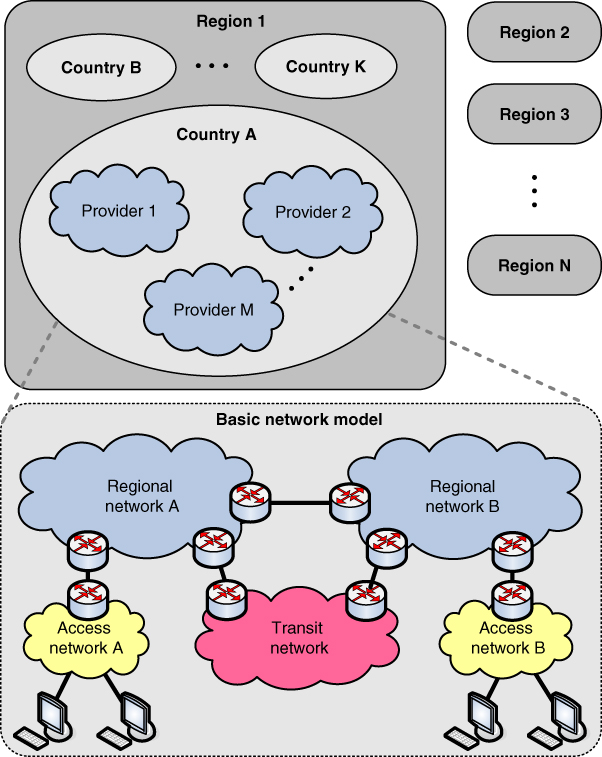
[Figure 2.4](https://learning.oreilly.com/library/view/qos-for-fixed/9781119470502/c02.xhtml#R_c02-fig-0004) Basic network model for QoS analysis.
### 2.2.4 Autonomous Systems on the Internet
The Internet as a global network is built on the principle of a network of many networks that are interconnected through routers. Certainly, there must be routers between different IP networks. However, several smaller or larger networks can be administered by a company, such as an Internet service provider. In this case we actually have independently operated networks. Each of these networks of networks (where a network is identified by a unique routing prefix or network ID, which is the part of the IP address that is the same for all network interfaces attached to the given IP network) actually forms an autonomous system. So, an AS is a collection of routers under the control of one authority (a company, telecom operator, etc.). These ASs are connected with each other through gateway routers to the Internet (i.e. to other ASs). Each AS is identified via a 16‐bit or 32‐bit AS number, where AS numbers are globally allocated and managed by IANA.
With ASs as the basic architectural approach at present, we actually have two‐tiers routing on the Internet [[17]](https://learning.oreilly.com/library/view/qos-for-fixed/9781119470502/c02.xhtml#c02-bib-0017):
- _Intra‐AS routing_. This is between routers belonging to a single AS (e.g. Routing Information Protocol (RIP), Open Shortest Path First (OSPF)).
- _Inter‐AS routing_. This is routing between routers belonging to different ASs. Currently, the globally accepted protocol for inter‐AS routing is BGP‐4 (Border Gateway Protocol version 4).
So, while different routing protocols for routing inside a given AS can be used, the one used for routing between different ASs (inter‐AS routing) is the same everywhere: BGP‐4. BGP is in fact the “glue” that connects all autonomous parts of the global Internet network.
How does BGP work? It is not a typical routing protocol which uses the shortest path routing principle, it is also based on policies that are influenced by business decisions about peering of the given network with other networks. BGP routers are typically implemented at the edge of the AS (toward the outside Internet network, from the AS's point of view), and they advertise (to other BGP routers with which they have an established BGP peering connection) reachability of other ASs or IP network prefixes through them.
The Internet has become more global and interlinked over time, while at the same time dependence on the largest ISPs has decreased. The number of ASs continues to grow [[21]](https://learning.oreilly.com/library/view/qos-for-fixed/9781119470502/c02.xhtml#c02-bib-0021). However, the average path length, which is expressed as a number of AS hops (not router hops), is stable [[21]](https://learning.oreilly.com/library/view/qos-for-fixed/9781119470502/c02.xhtml#c02-bib-0021). This implies that ASs are more richly connected than in the past. In 2017, the entire Internet consisted of approximately 60 000 active ASs, with the average path length (end‐to‐end) span across 3–5 ASs. Regarding end‐to‐end QoS, more ASs on the path of the IP packets (i.e. the traffic) add more delay and a higher probability of bottlenecks somewhere on the path between the endpoints of a communication call/session. This shows that the Internet has good scalability, that is, with its increase in size, the number of ASs that the traffic passes end‐to‐end remains almost the same, which directly influences the end‐to‐end QoS (fewer ASs on the path is better).
The different types of ASs lead to different types of business relationships between them, which in turn translate to different policies for exchanging and selecting routes. Overall, there are two main types of exchange of traffic between ASs at inter‐As interconnections [[22]](https://learning.oreilly.com/library/view/qos-for-fixed/9781119470502/c02.xhtml#c02-bib-0022):
- _Transit_. In this case one ISP provides access to most or all destinations in its routing tables. Transit is typically based on financial settlement for an inter‐AS relationship where the provider ISP charges its customers (other ISPs or companies which have their own ASs) for forwarding/routing their IP packets on behalf of customers to destinations (and vice versa).
- _Peering_. In this case two ASs (which are typically ISPs) provide mutual access to a subset of each other's routing tables. Similar to the transit, the peering is also a business deal; however, it may be set up without particular financial settlement. There are also cases for paid peering in some parts of the world, though in most of those cases it is based on reciprocal agreements. That is acceptable from a business point of view in cases where the traffic ratio between the concerned ASs is not highly asymmetric (e.g. a ratio of 1:4 may be considered as some boundary [[22]](https://learning.oreilly.com/library/view/qos-for-fixed/9781119470502/c02.xhtml#c02-bib-0022)).
Large network operators (such as national telecom operators) typically exchange traffic with other comparably large network operators through private peering arrangements, which are based on direct connections between the operators. Such peering agreements are usually subject to contracts and to certain nondisclosure commitments.
In terms of the amount of Internet traffic carried through peering interconnections, they are very important because most of the Internet traffic travels across them. In the 2010s it is becoming common for interconnection between IP networks of large network operators to be realized via Internet Protocol eXchange (IPX) points on a national or international level, which are typically used by operators in a given country or region.
## 2.3 Internet Traffic Characterization
There are different applications/services present on the public Internet. Also, there are different requirements for telecom‐provided services over managed IP networks, with certain guaranteed QoS and based on signed agreements with customers (e.g. fixed or mobile telephony and TV, business services). All Internet packets on a given network interface (e.g. on a host, on a router), or in a given network or a network segment, are referred to as IP traffic. The traffic notion comes from legacy telecommunication networks, where it was used to denote mainly voice traffic (in PSTNs).
There are different traffic classifications. Although there are many different applications for traffic nowadays (e.g. millions of applications are available in different ecosystems of global OTT service providers), they all can be grouped into three main types: audio, video, and data. The first two, audio and videos, are based upon the human senses and their “design” for hearing (audio) and viewing (video), while the data traffic type includes everything else. Each of these traffic types has specific traffic characteristics which influence network performances and QoS solutions. So, typically we have the following types of traffic on the Internet:
- _Voice traffic_. This is conversational type of traffic (with similar requirements in both directions, from calling party A to called party B, and vice versa) and has constant bitrate when sending or receiving. Also, voice requires relatively small IP packets (e.g. 50–200 bytes).
- _Video traffic_. This generally has high variable bitrate, which is dependent upon the codec efficiency of the moving pictures (e.g. Moving Picture Experts Group (MPEG‐2), MPEG‐4 various codec types). Video is typically unidirectional traffic (in downstream, i.e. downlink, direction regarding the end‐user), so it can use the largest possible IP packets since it can eliminate IP packet delay variations with delayed playback on the receiving side. Since local access to the Internet in homes, offices, or public places is unified to Ethernet or WiFi (except in mobile networks), the maximum IP packet size for video traffic is limited by the MTU (message transfer unit) of Ethernet (and similarly WiFi), which is 1500 bytes.
- _Data traffic_. This is typically the non‐real‐time (NRT) traffic on the Internet, the most prominent examples being the WWW and email. This type of traffic is typically TCP‐based (regarding transport protocol, which goes over IP, thus giving TCP/IP).
### 2.3.1 Audio Traffic Characterization
Audio traffic usually refers to voice. The conversational voice (i.e. telephony) is most sensitive to delay and jitter. Regarding telephony, the recommended delay in PSTN is below 150 ms, while above 400 ms is not acceptable because the people talking will start interrupting each other [[23]](https://learning.oreilly.com/library/view/qos-for-fixed/9781119470502/c02.xhtml#c02-bib-0023). However, in IP environments the delay is always higher than in PSTN/ISDN due to packetization (creation of IP packets with payload many times bigger than the IP header due to efficiency reasons, that is, lower redundancy), buffering in network nodes (every router first buffers the packets and then sends them over a given network interface on the next hop, which is different than PSTN where bits and bytes are being transferred from one end to the other end without any notable buffering), propagation delay (due to limited speed of the signals, which is always around the speed of light on any transmission media), and so on.
In all‐IP environments, different packets may enter buffers with different queue length, which may introduce different delays to IP packets from the same end‐to‐end connection. The average delay variation is also referred to as jitter. To compensate for the jitter, the voice has a playback point, similar to video.
However, audio is more tolerant to errors than video due to the human ear, which is more error resistant (up to several percent of the error ratio). Audio must synchronize with video in multimedia communication, such as real‐time video streaming (with audio typically synchronized with the video content), video telephony (voice as audio traffic, with synchronized video, in both directions), etc.
Because voice is a two‐way continuous audio streaming with strict delay requirements, it is typically carried by using RTP/UDP/IP protocol stack. The voice is a most typical example of real‐time traffic. However, there are differences in how the voice is treated when provided by telecom operators with guaranteed QoS and when it is being provided as any other data by OTT voice service providers (e.g. Skype, Viber, WhatsApp) over the public Internet.
### 2.3.2 Video Traffic Characterization
Most of the video traffic is based on video information which is statistically compressed. The statistical compression is performed by source coding in the video codec (includes video coder on the sending side and video decoder on the receiving side). The most used video codecs nowadays are based on the MPEG‐4 standard. Before this came its predecessors, MPEG‐2 targeted to DVD‐quality video, which was also used for transmission over telecommunication networks, and MPEG‐1, which was used for recording video on storage media only (not suitable for transmission over telecommunication networks).
The MPEG standards, from MPEG‐1 and further in MPEG‐2 and MPEG‐4, follow the same pattern regarding compression of the video content. Typically the video is organized in series of pictures (called frames) which appear 25 or 30 times per second (at equidistant time intervals), according to the legacy TV standards from the twentieth century. Each such picture is compressed by removing its redundancy with respect to other parts of the same picture or in regard to other neighboring pictures. In MPEG standards there are reference pictures, which are not coded in respect to the other pictures (i.e. frames), and such frames are highest in size and are referred to as “I” frames (according to the MPEG terminology). Besides the reference frames, there are “P” pictures, which are compressed by removing temporal redundancy in respect to neighboring “I” frames. Finally, MPEG also has “B” pictures in which temporal redundancy in respect to neighboring “P” and “I” frames is removed. Hence, “B” frames are on average smallest, while “P” frames have sizes between the size of “B” and “I” frames, and “I” frames have the largest average size. Of course, all pictures are also spatially compressed by removing as much as possible of their own redundancy.
Why is the approach used in video codecs such as MPEG important for video traffic? From the 1990s onwards almost all video codecs were based on various versions of the MPEG standards. For example, MPEG‐4 is currently the most used video coding standard (it also includes audio coding, where audio typically accompanies the video traffic) and it absorbs all features of the previous MPEG standards (note that there is no MPEG‐3 standard). In fact, MPEG‐4 is an umbrella standard, which was standardized in 1998 by ISO (International Organization for Standardization); since then many new parts of the standards have been standardized (over 30 such parts of MPEG‐4 were standardized by ISO in the first two decades after the initial standard and their number continues to grow). Then, bearing in mind the type of pictures in MPEG, i.e. “I”, “P,” and “B” frames, one may conclude that there will be variations in sizes of frames of different types as well as of the same type due to different video content and different compression possibilities. So, all digital video content is compressed with source (statistical) coding techniques before transmission (or such video files are stored on video content servers), which results in highly varying bitrates for video.
Because video traffic has high peak to mean ratio, in telecommunication networks it may be shaped (up to predefined maximum bitrates), which is typical in cases when video content over managed IP‐based networks (not part of the public Internet) is provided with QoS guarantees end‐to‐end (e.g. IPTV services provided by telecom operators). Such video traffic shaping is shown in Figure [2.5](https://learning.oreilly.com/library/view/qos-for-fixed/9781119470502/c02.xhtml#c02-fig-0005).
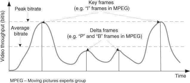
[Figure 2.5](https://learning.oreilly.com/library/view/qos-for-fixed/9781119470502/c02.xhtml#R_c02-fig-0005) Video traffic shaping and effect of the packet delay.
At the receiving side, the application (e.g. video player) buffers the video data with the aim of ensuring consistency in the reproduction of the video content. So, playback point is introduced with a certain delay in respect of the average delay of the packets to compensate for the delay variation of most of the packets. Figure [2.6](https://learning.oreilly.com/library/view/qos-for-fixed/9781119470502/c02.xhtml#c02-fig-0006) shows the typical positioning of the playback point and typical probability distribution function of IP packet delays for video traffic. It is up to the video player to calculate the playback point to provide smooth watching of the content by the end‐user (however, this is dependent upon the availability of consistent bitrate end‐to‐end from the video sender downstream to the video player of the end‐user).
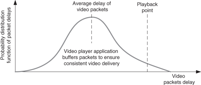
[Figure 2.6](https://learning.oreilly.com/library/view/qos-for-fixed/9781119470502/c02.xhtml#R_c02-fig-0006) Video playback point.
Most of the live video traffic is based on the RTP/UDP/IP protocol stack. However, with the availability of broadband access to the Internet, many video sharing sites provide content by using the HTTP/TCP/IP protocol stack, with longer delays for playback point due to retransmission of all lost segments by TCP. Also, proprietary transport protocol implementations, based on certain characteristic of UDP (e.g. datagram transfer) and TCP (e.g. acknowledgments and retransmissions of lost IP packets), are being used for video traffic (e.g. for IPTV). However, video streaming (as unidirectional video, from video servers toward the video player of the end‐user) is also considered as a real‐time service, although it has less strict end‐to‐end delay requirements when compared with voice (e.g. it can tolerate delays up to several seconds).
### 2.3.3 Non‐Real‐Time Traffic Characterization
NRT traffic has no strict requirements on delay. Such traffic may include applications which are interactive (e.g. Web, FTP) or message based (e.g. email). Most of this NRT traffic is carried by using TCP/IP protocol stack, so it has lossless transmission end‐to‐end, which is provided by TCP on the transport layer at the end hosts (e.g. Web browser and Web server as two end sides for Web communication). NRT is considered to be one of the main reasons for Internet congestion at bottlenecks in the networks for a given connection end‐to‐end (a bottleneck may appear anywhere in access, core, or transit networks). Congestion typically appears on network interfaces when all packets that should be sent through them cannot be sent in the required time interval, which results in long buffer queues and finally in packet losses (packets are dropped when the buffers are filled over a certain threshold).
What are the reasons for Internet congestion? Well, most Internet traffic is TCP‐based (and the rest is UDP) because the dominant type of traffic is from the WWW and Web‐based services, including here also video and picture sharing sites, and other multimedia sharing websites. TCP congestion control mechanisms assure maximal utilization of bottleneck (Figure [2.7](https://learning.oreilly.com/library/view/qos-for-fixed/9781119470502/c02.xhtml#c02-fig-0007)), so TCP traffic flow consumes all available bitrate (i.e. bandwidth) which is limited by the bottleneck anywhere on the end‐to‐end path of the packets. If there are 10 TCP file downloads (e.g. Web based) over a 10 Mbit/s link (as a bottleneck link), then after enough time each of the TCP flows will have up to approximately 1/10th of the total available bandwidth (i.e. bitrate). TCP mechanisms do not allow TCP to use 100% of any link bandwidth because CWs in most TCP implementations are never constant – either they rise until a packet loss occurs, or they decrease after losses (e.g. due to fast retransmission and fast recovery, or due to TCP timeout and then slow start phase).
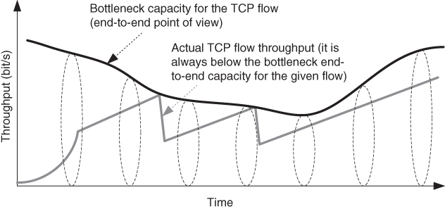
[Figure 2.7](https://learning.oreilly.com/library/view/qos-for-fixed/9781119470502/c02.xhtml#R_c02-fig-0007) TCP behavior at congestion.
TCP mechanisms at the end‐hosts are completely independent of the functions of the network nodes (e.g. switches and routers) and hence accidentally may cause congestion. That results in long queues without a control mechanism (under assumed heavy congestion at the given network node). The congestion creates back‐to‐back packet losses, which may trigger two or more losses in a given TCP CW (for each TCP connection which goes through that congestion bottleneck). This arises from multiple loss behavior of TCP, and may result in TCP timeouts and entering the slow start phase, which results in higher oscillations in the bitrate of a given connection. In an attempt to avoid multiple packet losses from a single TCP connection as much as possible, network nodes (such as routers) implement random discard of packets (from various positions in the buffer queue) when the buffer is filled over a certain upper congestion threshold (e.g. 80% filled buffers).
Summarizing Internet congestion, it is mainly due to TCP, which is implemented and controlled by end‐user devices (i.e. hosts, including clients and servers). Then the question is how to provide QoS guarantees to this NRT traffic, which is TCP‐based. That can be accomplished either by adding certain QoS mechanisms in an initially best‐effort Internet network or by ensuring that sufficient capacity is available.
So, something that was the main Internet networking paradigm (simple network which uses the best‐effort principle for transfer of packets, and complex hosts which deal with congestion that may occur anywhere along the path between the endpoints of communication by using TCP at the end‐hosts) is becoming one of the main obstacles for provision of QoS in the network end‐to‐end for NRT traffic.
## 2.4 QoS on Different Protocols Layers
The networking protocols in all‐IP telecommunication networks are based on IP on the network layer and on TCP or UDP on the transport protocol layer. The lowest protocol layer in the protocol stack which functions end‐to‐end is the network layer, where the IP is positioned in all hosts and network nodes (e.g. routers). End‐to‐end means that the sending hosts creates an IP packet which may be received as a whole (IP packet) through the Internet by the receiving host. Of course, certain types of network nodes may change the contents of the IP packet, such as NAT (network address translation) gateways or proxies along the path. So, network layer QoS is related to the IP in both IPv4 and IPv6. However, protocols over and below the IP layer influence the QoS being provided.
The performance of IP‐based services depends upon the performance of other protocol layers below or above the IP. Regarding the lower protocol layers (below IP), these belong to certain links (e.g. between two network elements such as routers and switches, or between network elements and end‐hosts) which provide connection‐oriented or connectionless transport for the IP layer (i.e. IP packets). In general, links between hosts and/or nodes in telecommunication networks may be based on different types of technologies, such as Ethernet, WiFi, mobile RANs, and optical links.
Higher protocol layers (above IP) include the transport protocol layer and above (e.g. presentation, session, and application layers, usually treated on the best‐effort Internet as a single application layer), which include protocols (on those layers) such as TCP, UDP, RTP on the transport layer, HTTP, FTP, SMTP, POP3, and proprietary (not standardized) applications on the application layer. Higher layers may also influence the end‐to‐end performance (e.g. TCP provides congestion control end‐to‐end by the end‐hosts, while RTP provides two‐way control information needed for real‐time services). Transport and network layer protocols are implemented in the OSs of the end‐user equipment, so their implementation (e.g. TCP implementation) may influence the behavior of applications and services on the top. For example, different OSs may provide different user experiences at the same network conditions (throughput, congestion, etc.) due to different versions of TCP.
There are interrelationships of the QoS parameters on different layers, such as the link layer, network layer, and application layer (Figure [2.8](https://learning.oreilly.com/library/view/qos-for-fixed/9781119470502/c02.xhtml#c02-fig-0008)). For example, link layer performance influences QoS, including the technology used for the given link (e.g. whether it is Ethernet or mobile access, and so on), as well as its QoS mechanisms and congestion occurrence at a given time period. Network factors, such as packet loss, jitter, or delay, in different networks as packets travel between the end‐hosts influence the application factors, which may include overall packet loss, overall delay, end‐to‐end average jitter, and codec performance (for the given media type, such as audio or video). The overall end‐to‐end application factors directly influence the perceived quality, which may be measured and discussed only end‐to‐end, at the point where the user is located. So, one may note that there is some interrelationship among QoS parameters on different protocol layers.
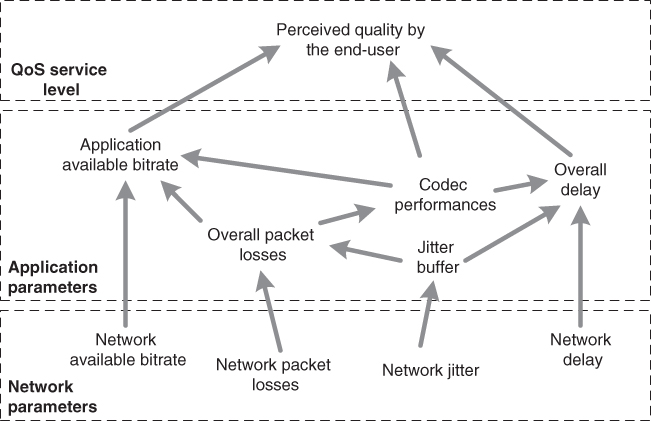
[Figure 2.8](https://learning.oreilly.com/library/view/qos-for-fixed/9781119470502/c02.xhtml#R_c02-fig-0008) Interrelationship of QoS parameters.
## 2.5 Traffic Management Techniques
When there is heterogeneous traffic over the same IP network, the issue is what to do with different traffic types on public or/and non‐public networks. On one side, the Internet was initially designed to provide best‐effort service, i.e. all IP packets are treated in the same manner. On the other side, not all packets are the same. For example, the Web as an interactive application is delay sensitive, but voice is more sensitive to delay and jitter. Video requirements are highest regarding bitrate because video is one of the most demanding traffic types on the Internet. Also, online games are delay and jitter sensitive, even more than voice. Some P2P applications for file sharing, where BitTorrent was the most used at the beginning of the twenty‐first century [[17]](https://learning.oreilly.com/library/view/qos-for-fixed/9781119470502/c02.xhtml#c02-bib-0017), are generally insensitive to delay and jitter, while bandwidth does not matter a lot for them, although it is still important (e.g. file transfer will finish eventually, but having higher average download bitrate will help the user to be more satisfied with it). There are other examples, but the main points are given. This “big picture” refers to the public Internet, which is also referred to as Internet access service by many regulators and telecom operators.
When all IP traffic is multiplexed onto the same IP‐based links and IP networks, including traditional telephony (as VoIP) and television (as IPTV), then the network needs to have techniques to give better quality to some packets for certain types of applications/services.
### 2.5.1 Classification of IP Packets
How do we classify IP packets? Well, it depends on the approach used, and there are different options on the table, which may include (but are not limited to) the following:
- _Classification based on ports_. Ports are used by transport layer protocols such as TCP and UDP to identity applications on the top. For example, port 80 (HTTP, i.e. the Web) may take precedence over port 21 (FTP).
- _Classification based on application type_. Different applications may be treated differently. For example, carrier grade VoIP takes precedence over HTTP, BitTorrent, and other OTT services used over Internet access service.
- _Classification based on user type_. There are typically different types of users of telecommunication services. For example, home and business users may get normal service, but hospitals, police, or fire departments get highest priority service and no mandatory requirement for users' authentication (e.g. emergency services number 112 in Europe, or 911 in the U.S.).
- _Classification based on subscription_. Different users may pay different prices for the same services with different QoS. For example, a user may need to pay $50 for high‐speed Internet access (with guaranteed maximum access bitrates in downstream and upstream) and $10 for fair‐usage policy‐based Internet (e.g. bitrates are proportionally downgraded with higher usage).
Besides the above classification of IP packets and sessions or calls to which they belong, there are other options and possibilities which may be created for classification of user traffic and hence IP packets. Regardless of the approach used, it is always implemented via certain traffic management techniques. Thus there is technical classification of IP packets which is similar to port‐based classification.
### 2.5.2 Packet Classification From the Technical Side
Packet classification is needed to sort packets into flows and then to group the flows into classes. This is further needed for scheduling purposes, such as FIFO (first in first out), PQ (priority queuing), or some of many other techniques. Considering the Internet networking principles, based on identification of a connection with the IP address and the port number (regarding both sides of the connection, the sending side and the receiving side), usually the following fields are used for classification (called 5‐tuple):
- source address (from the IP header), which identifies the network interface of the sender;
- destination address (from the IP header), which identifies the network interface of the recipient;
- protocol type, such as TCP or UDP (read from the field “protocol number” in the IPv4 header or the “next header” field in the IPv6 header);
- source port (from the transport protocol header, e.g. the TCP or UDP port number);
- destination port (from the transport protocol header, e.g. the TCP or UDP port number).
In IPv6 networks, classification can be performed also with 3‐tuple in cases where “Flow Label” in the IPv6 header is used. In such cases the 3‐tuple is the:
- source IPv6 address;
- destination IPv6 address;
- “Flow Label” field from the IPv6 header, which identifies the flow, and in which case there is no need for use of port numbers from the transport layer protocol header.
After classification of IP packets, the next step is packet marking. The packets are typically classified and marked at the edge routers. After an IP packet enters the core network, core routers check the mark applied by the edge routers.
### 2.5.3 Packet Scheduling
Packet scheduling typically refers to mechanisms in network nodes (e.g. routers) regarding how to schedule the IP packets on the same outgoing interface (toward the next hop, which is the next router on their path). There are many scheduling mechanisms defined, and subsets of them are implemented by different vendors (in network equipment, such as routers, switches, mobile base stations). The typical default scheduling scheme is FIFO (sometimes called FCFS (first come first served)), which gives priority to the IP packets which first enter the buffer queue for the given outgoing network interface. FIFO suits the best‐effort nature of Internet traffic, with the initial low cost of the networking equipment because no additional traffic management mechanisms are deployed.
However, when broadband IP access is used for both managed IP traffic (with QoS guarantees) and best‐effort traffic over the Internet access service (for access to the public Internet), then there is a need for differentiation of traffic in the scheduling mechanism, so IP packets belonging to one traffic type (or class) will be served before packets of other traffic types (or classes). For example, delay‐sensitive applications and services, which are referred to as real‐time traffic, should be given priority over NRT traffic, which can tolerate longer delays (although not too long for most of the NRT services, for example Web browsing). Priority queuing is used for this purpose.
Priority queuing is the simplest and most commonly technique used to differentiate between traffic types (e.g. VoIP, IPTV, and best‐effort Internet traffic). It places traffic into different queues and serves them in priority order (e.g. high priority for VoIP, medium for IPTV, and low for best‐effort packets, as shown in Figure [2.9](https://learning.oreilly.com/library/view/qos-for-fixed/9781119470502/c02.xhtml#c02-fig-0009)).
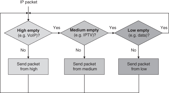
[Figure 2.9](https://learning.oreilly.com/library/view/qos-for-fixed/9781119470502/c02.xhtml#R_c02-fig-0009) Priority queuing for VoIP, IPTV, and Internet access service.
Overall, there is no single best scheduling mechanism. Which is best depends upon the traffic being scheduled, offered service packages to end‐users, available bandwidth, traffic management techniques being used (e.g. traffic shaping for limiting the bitrate allocated to a given traffic type of a given IP flow), etc. Therefore, typically, scheduling mechanisms are not usually standardized; rather, it is left to the vendors to provide different scheduling options in the network equipment, and then to network designers on the side of telecom operators (i.e. network providers) to create traffic management solutions that best fit the given network and the telecom business regarding the offered services to their customers.
### 2.5.4 Admission Control
No matter how good the scheduler is, one may still have no QoS in practice. Why? Because when traffic demand exceeds available resources (i.e. bandwidth – bitrates in an uplink or downlink direction), there will be congestion, which means that QoS requirements cannot be maintained. With the aim of providing QoS, it is always necessary to provide more resources than those that can be spent (also referred to as overprovisioning) or to provide admission control (which means that the number of simultaneous connections over a given network link is limited, subject to the network design).
What is admission control? It is a traffic management technique which is used to reject a flow (a call or a session) if there are insufficient resources (e.g. in the access, core, or transit network). It is different from traffic policing (which is used to reject/drop a packet). For example, in the traditional telephone networks (e.g. PSTN, Public Land Mobile Network (PLMN), it is easy to manage admission control. Why? Due to circuit‐switching (allocation of a pair of channels per call, i.e. fixed resources per call). Then, teletraffic engineering provides an efficient means for planning the telephone networks (e.g. the well‐known Erlang‐B formula for calculation of the number of channels required to serve certain traffic intensity under the given maximum acceptable new call blocking rate).
Internet flows from different applications/services have different QoS requirements. Therefore, admission control is much harder for implementation in IP‐based environments where the same network is used for transfer of packets from many different services, each with potentially different QoS requirements and hence different admission control approaches.
Let us analyze a typical example at a telecom operator when multiple services are offered though broadband access, such as VoIP service, IPTV service, and Internet access service. If an average requirement per VoIP is 100 Kbit/s in each direction, IPTV service with standard definition (SD) quality requires up to 3 Mbit/s reserved bitrate (with traffic shaping of the video flow) per piece of end‐user equipment (e.g. IPTV user equipment, such as a setup box), and there is 10 Mbit/s per second overall in the downlink direction, then there can be a maximum of three pieces of IPTV user equipment connected, with the aim of guaranteeing QoS for the IPTV. Also, more bandwidth dedicated to IPTV will result in less bandwidth (bitrate) in the downlink direction for the Internet access service. On the other side, services and applications offered through the Internet access services are not subject to admission control due to the network neutrality principle for the public Internet, and hence there is no admission control for the number of flows that can be established over it (e.g. a user can open different videos even in different browser tabs, and when the available bandwidth is consumed it will result in congestion, which will cause videos to freeze at a certain time period or constantly).
Overall, admission control is directly related to QoS provisioning per flow or per traffic class (where a class denotes traffic aggregated from many flows from the same traffic type carried over the same links or networks).
### 2.5.5 Traffic Management Versus Network Capacity
The extent and complexity of traffic management are associated with how much congestion is being experienced or how close network traffic is to the limit of the network's capacity, as given in Figure [2.10](https://learning.oreilly.com/library/view/qos-for-fixed/9781119470502/c02.xhtml#c02-fig-0010).
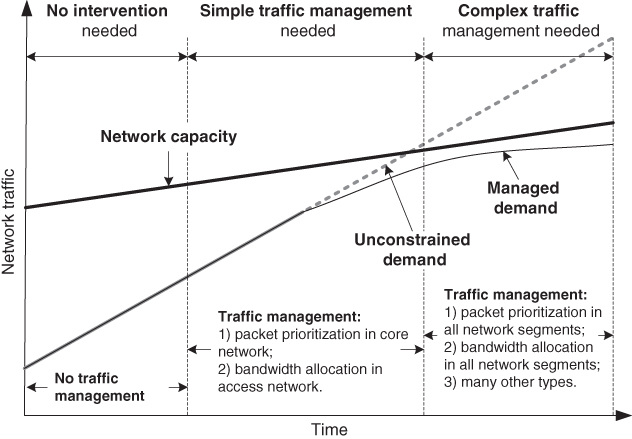
[Figure 2.10](https://learning.oreilly.com/library/view/qos-for-fixed/9781119470502/c02.xhtml#R_c02-fig-0010) Traffic management versus available network capacity.
When traffic demand is much lower than the installed network capacity, there is no need for intervention. When there is moderate “space” between demand and available network capacity, simple traffic management is needed, which includes bandwidth allocation and packet prioritization. When traffic demand approaches network capacity, the probability of traffic congestion increases significantly. In that case, traffic management is strongly required to improve QoS.
In the long term, from a technical point of view, one may expect traffic management to remain as the main toolset for a response to congestion, as well as to maintain the highest possible level of QoS. One of the most important changes will be that packet inspection capabilities will migrate out of the core network toward the access networks, enabling a more finely graded and user‐specific form of traffic management [[24]](https://learning.oreilly.com/library/view/qos-for-fixed/9781119470502/c02.xhtml#c02-bib-0024).
Overall, there are positive and negative effects of traffic management applied in the network, which are summarized in Table [2.1](https://learning.oreilly.com/library/view/qos-for-fixed/9781119470502/c02.xhtml#c02-tbl-0001) [[24]](https://learning.oreilly.com/library/view/qos-for-fixed/9781119470502/c02.xhtml#c02-bib-0024).
[Table 2.1](https://learning.oreilly.com/library/view/qos-for-fixed/9781119470502/c02.xhtml#R_c02-tbl-0001) Traffic management: positive and negative effects on QoS.
||Positive effects on QoS|Negative effects on QoS|
|---|---|---|
|Traffic management applied to user's traffic|Can guarantee or prioritize data for delay‐sensitive or bandwidth‐demanding applications|Can restrict traffic from certain applications|
|Traffic management applied to other users' traffic|Can reduce congestion, allowing fair use for all users|Other users' traffic may take priority over user's own traffic|
## 2.6 Internet QoS Frameworks: the IETF and the ITU
Internet technologies are standardized by the IETF (e.g. IP, TCP, UDP, HTTP, DHCP, DNS, i.e. all important protocols on the Internet are Internet standards). The standards are required with the aim of making different vendors of hardware (e.g. network equipment, user equipment) and software (e.g. OSs, some applications such as Web browsers) interoperable.
The IETF standardized several QoS solutions in the 1990s, which provided an early Internet QoS standardization landscape. According to those standards and default traffic management principles used on the public Internet, one may distinguish an IETF Internet QoS framework consisting of the following approaches (including accepted scenarios and standardized mechanisms):
- _Best effort_. This is the traditional Internet model, without any QoS guarantees. The IP networks simply route packets until they reach their destination.
- _Integrated services (IntServ)_ [[25]](https://learning.oreilly.com/library/view/qos-for-fixed/9781119470502/c02.xhtml#c02-bib-0025). This was the first mechanism standardized by the IETF, based on resource reservation in routers on the path by using signaling. So, routers have to store traffic and QoS information per connection (i.e. per flow). It is an end‐to‐end QoS mechanism.
- _Differentiated services (DiffServ)_ [[26]](https://learning.oreilly.com/library/view/qos-for-fixed/9781119470502/c02.xhtml#c02-bib-0026). This is the most commonly used method for traffic differentiation, in which all packets are classified into a limited number of classes, so routers have to store only information per class (not per connection/flow). It is a hop‐by‐hop QoS mechanism.
- _Multi‐protocol label switching_ _(__MPLS__)_ [[27]](https://learning.oreilly.com/library/view/qos-for-fixed/9781119470502/c02.xhtml#c02-bib-0027). This is the “default” approach for QoS provisioning in transport IP networks, which may be combined with DiffServ as well as other protocols such as BGP, or VPN protocols.
- _Policy‐based QoS_. This is typically used for QoS provisioning between network providers (e.g. BGP policies are used for routing of packets between interconnected ASs).
The ITU has also defined a QoS framework for telecommunication packet‐switched networks (where the Internet and Internet networking technologies belong). As usual, since the PSTN/ISDN era, the ITU‐T QoS architectural framework is organized into three planes [[28]](https://learning.oreilly.com/library/view/qos-for-fixed/9781119470502/c02.xhtml#c02-bib-0028) (Figure [2.11](https://learning.oreilly.com/library/view/qos-for-fixed/9781119470502/c02.xhtml#c02-fig-0011)):
- _Control plane_. This includes the admission control, QoS routing, and resource reservation.
- _Data plane_. This includes several traffic management aspects such as buffer management, congestion avoidance, packet marking, queuing and scheduling, traffic classification, traffic policing, and traffic shaping.
- _Management plane_. This includes service level agreement (SLA), traffic restoration, metering and recording, and policies.
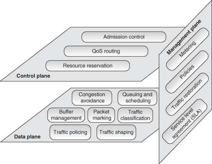
[Figure 2.11](https://learning.oreilly.com/library/view/qos-for-fixed/9781119470502/c02.xhtml#R_c02-fig-0011) QoS architectural framework by the ITU.
So, overall the ITU QoS framework includes all IETF standards on Internet QoS and puts them into the well‐established telecommunication concept, which is based on the three planes. This way there is synergy between the standardization efforts on QoS by both standards development organizations (SDOs), the IETF and the ITU, which is beneficial to telecommunication/ICT networks and services which are converging on the Internet networking principles and Internet technologies for service provisioning.
## 2.7 Integrated Services (IntServ) and Differentiated Services (DiffServ)
Integrated Services (IntServ) is an architecture for providing QoS guarantees in IP networks for individual application sessions. It relies on use of Resource Reservation Protocol (RSVP) [[29]](https://learning.oreilly.com/library/view/qos-for-fixed/9781119470502/c02.xhtml#c02-bib-0029) and routers need to maintain records of allocated resources and to respond to new call setup signaling requests. In IntServ architecture every router between the two end‐hosts which needs to establish a session must reserve required resources (e.g. bandwidth) by using the QoS call setup signaling, as shown in Figure [2.12](https://learning.oreilly.com/library/view/qos-for-fixed/9781119470502/c02.xhtml#c02-fig-0012).
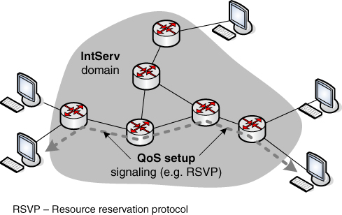
[Figure 2.12](https://learning.oreilly.com/library/view/qos-for-fixed/9781119470502/c02.xhtml#R_c02-fig-0012) QoS call setup signaling for integrated service (IntServ).
Another IETF QoS standard on the network layer is the Differentiated Services (DiffServ) architecture [[30]](https://learning.oreilly.com/library/view/qos-for-fixed/9781119470502/c02.xhtml#c02-bib-0030), also defined in the 1990s (in 1998, after IntServ). DiffServ divides the Internet traffic into different classes, called behavior aggregates (BAs), and gives them differentiated treatment regarding QoS provisioning. It is based on per‐hop behavior (PHB), which is in fact the externally observable forwarding behavior applied at a DiffServ‐compliant node to a DiffServ behavior aggregate. The IETF's development of DiffServ in the 1990s was intended to address the following difficulties with IntServ and RSVP:
- _Scalability_. Maintaining states by routers in high‐speed networks is difficult due to the very large number of flows.
- _Flexible service models_. IntServ includes only two classes, and there was a need to provide more qualitative service classes and “relative” service distinction.
- _Simpler signaling (compared with RSVP)_. Many applications and users may only want to specify a more qualitative notion of service.
Which are DiffServ functions? Well, it provides only simple functions in the core network (forwarding according to the PHB) and relatively complex functions at edge routers (or hosts). A DiffServ‐capable host or first DiffServ‐capable router requires the following actions (Figure [2.13](https://learning.oreilly.com/library/view/qos-for-fixed/9781119470502/c02.xhtml#c02-fig-0013)):
- _Classification_. Network edge node marks packets according to classification rules to be specified (manually set by network administrators, or by some protocol);
- _Traffic conditioning_. Network edge node may delay and then forward, or they may discard packets.
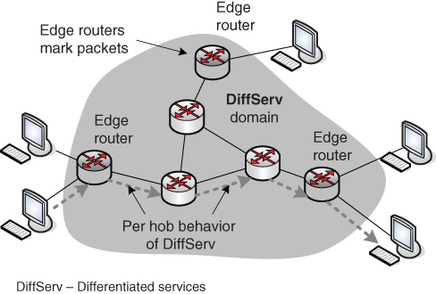
[Figure 2.13](https://learning.oreilly.com/library/view/qos-for-fixed/9781119470502/c02.xhtml#R_c02-fig-0013) Differentiated services (DiffServ) functions.
In DiffServ, IP packets are marked in the IP headers, so this is truly a network‐layer QoS mechanism (there is no need to read or change upper layer headers such as protocols on the transport or application layer). The marking in IP headers is completed by the edge routers in the DiffServ network domain (that is the network that implements DiffServ architecture) by marking specified fields in the IP headers:
- ToS field in the IPv4 header, and
- DSCP in the IPv6 header.
It may be desirable to limit the traffic injection bitrate of some classes, in which case the user declares the traffic profile (e.g. rate and burst size). Then IP traffic is metered and shaped if non‐conforming (Figure [2.14](https://learning.oreilly.com/library/view/qos-for-fixed/9781119470502/c02.xhtml#c02-fig-0014)).
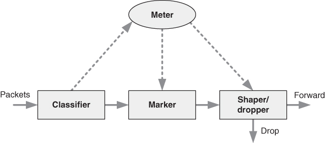
[Figure 2.14](https://learning.oreilly.com/library/view/qos-for-fixed/9781119470502/c02.xhtml#R_c02-fig-0014) Classification and conditioning of IP traffic.
Table [2.2](https://learning.oreilly.com/library/view/qos-for-fixed/9781119470502/c02.xhtml#c02-tbl-0002) compares best‐effort, DiffServ, and IntServ as QoS architectures. Best‐effort is simplest, but it does not provide any QoS differentiation between calls/sessions or aggregates of IP traffic. However, if there is enough bandwidth available, best‐effort can also provide services with satisfactory quality to end‐users. When comparing IntServ and DiffServ, the main difference is in the scalability of the two approaches. DiffServ is much more scalable because all routers keep information per traffic class (the number of traffic classes is limited and it is not related to traffic volume), while in the IntServ architecture the network nodes (routers) make first reservation of resources regarding required QoS and then maintain this information in network nodes on a per flow basis, which may lead to scalability problems (e.g. when there are many flows in parallel, which is typical in core and transport or transit networks).
[Table 2.2](https://learning.oreilly.com/library/view/qos-for-fixed/9781119470502/c02.xhtml#R_c02-tbl-0002) Comparison of best‐effort, DiffServ, and IntServ.
||Best‐effort|DiffServ|IntServ|
|---|---|---|---|
|Service|Connectivity <br>No isolation <br>No guarantees|Per aggregate isolation <br>Per aggregate guarantee|Per flow isolation <br>Per flow guarantee|
|Service scope|End‐to‐end|Domain|End‐to‐end|
|Complexity|No setup|Long‐term setup|Per flow setup|
|Scalability|Highly scalable (nodes maintain only routing state)|Scalable (edge routers maintain per aggregate state; core routers per class state)|Not scalable (each router maintains per flow state)|
## 2.8 QoS with Multi‐Protocol Label Switching (MPLS)
The main IETF approach standardized for QoS traffic management in transport networks is MPLS, with its standard defined in 2001 [[27]](https://learning.oreilly.com/library/view/qos-for-fixed/9781119470502/c02.xhtml#c02-bib-0027).
In IP transport networks with implemented MPLS (a typical scenario in transport IP‐based networks in the first two decades of the twenty‐first century), label switching is used instead of routing based on IP addresses. So, QoS is not implemented with DiffServ fields in the IPv4 or IPv6 headers, but by adding information via label headers (between the MAC header on layer 2 and the IP header on layer 3). MPLS works between OSI layers 2 and 3 (below the IP and above the MAC) and adds labels over the IP packet.
In IP/MPLS networks, label switching path (LSP) technology is used to pre‐provision a virtual multi‐protocol label switching transport network (VMTN) for each service type (VoIP, IPTV, best‐effort Internet traffic, corporate VPN, etc.). This can be performed manually (by setting the forwarding tables for MPLS) or automatically (by using RSVP for MPLS traffic engineering (RSVP‐TE) [[31]](https://learning.oreilly.com/library/view/qos-for-fixed/9781119470502/c02.xhtml#c02-bib-0031), or Constraint‐based Label Distribution Protocol (CR‐LDP), [[32]](https://learning.oreilly.com/library/view/qos-for-fixed/9781119470502/c02.xhtml#c02-bib-0032), DiffServ‐enabled MPLS traffic engineering (DS‐TE) for optimization purposes [[33]](https://learning.oreilly.com/library/view/qos-for-fixed/9781119470502/c02.xhtml#c02-bib-0033), as well as BGP/MPLS with IP VPNs [[34]](https://learning.oreilly.com/library/view/qos-for-fixed/9781119470502/c02.xhtml#c02-bib-0034) for IP traffic exchange (e.g. peering) between network providers (e.g. telecom operators).
Regarding the MPLS network architecture, in short, fixed‐length labels are associated to streams of data in the following manner (Figure [2.15](https://learning.oreilly.com/library/view/qos-for-fixed/9781119470502/c02.xhtml#c02-fig-0015)):
- In the ingress edge MPLS router, called LER (label edge router), labels are added to IP streams (based on different constraints for traffic differentiation at the network edges).
- Packet belonging to those streams are forwarded along the LSPs based on their labels (not on IP addresses), so there is no IP header examination in LSRs (label switching routers), which are used for packet switching in the MPLS network domain (that is, network segment or a whole network which uses and understands the labels added to the packets by LERs).
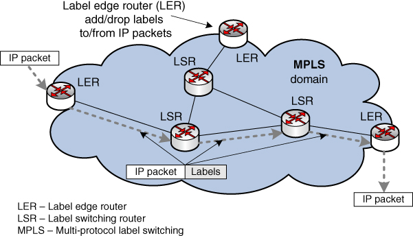
[Figure 2.15](https://learning.oreilly.com/library/view/qos-for-fixed/9781119470502/c02.xhtml#R_c02-fig-0015) MPLS network architecture.
QoS technologies based on the differentiated services architecture by using MPLS with VPN are widely deployed within the transport networks of many providers.
## 2.9 Deep Packet Inspection (DPI)
Deep packet inspection is a type of packet filtering targeted at all headers and all payloads from network layer (layer 3) up to application layer (layer 7), i.e. all layers that make up the end‐to‐end communication between the end‐hosts. However, in some cases layer 2 can be considered also in this group of layers for inspection. An illustration of DPI is given in Figure [2.16](https://learning.oreilly.com/library/view/qos-for-fixed/9781119470502/c02.xhtml#c02-fig-0016).
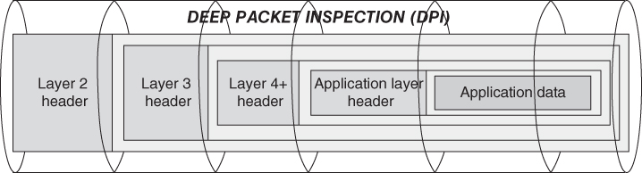
[Figure 2.16](https://learning.oreilly.com/library/view/qos-for-fixed/9781119470502/c02.xhtml#R_c02-fig-0016) Deep packet inspection (DPI).
The reasons for packet inspections may vary from case to case, so the targets may include finding viruses, spam, intrusions, or certain protocol non‐compliance, and so on. However, there can be other criteria associated with DPI filtering rules, which may include security as well as QoS topics.
In fact, DPI is directly related to the firewall concept, where firewalls have both types of implementation (stateful and stateless). Stateless refers to packet filtering where each packet is independently filtered in respect to other IP packets. Stateful inspection deals with the state of a given connection (e.g. between two end‐hosts, a client and a server). The state of the connections is a kind of vague definition because it very much depends upon the protocols being used (e.g. application layer protocols). In this regard, the DPI is in fact a stateful and dynamic packet inspection which identifies many applications and protocols (many times doing it with certain heuristic methods, i.e. not standardized ones, and methods being proprietary and developed by equipment vendors). DPI typically uses TCP and UDP port numbers as well as IP addresses in IP headers for matching packets belonging to the same connection (e.g. 5‐tuple can identify any IP connection), but also it may inspect non‐TCP and non‐UDP IP protocols by using data packet inspections for certain matching values.
What is the potential QoS role of DPI? Well, it can be used to provide classification of individual sessions and their application/traffic type, which may be needed for traffic management. Also, it can be used to provide differentiated charging (e.g. user traffic from/to certain OTT application not to be charged). It can be used to locate and then throttle some traffic (e.g. traffic from P2P file sharing), thus providing better QoS for the other OTT services offered via public Internet access.
Overall, one may note that DPI is implemented in different ways by different vendors of Internet network equipment (e.g. routers, gateways). However, the importance of DPI is also considered by the ITU‐T in its next generation network (NGN) series of recommendations. The requirements regarding DPI in NGN [[35]](https://learning.oreilly.com/library/view/qos-for-fixed/9781119470502/c02.xhtml#c02-bib-0035) are targeted (but are not limited to) to perform application identification by inspecting application payload, to support various kinds of policy rules, to be in line with IETF standards for IP flow information exports [[36]](https://learning.oreilly.com/library/view/qos-for-fixed/9781119470502/c02.xhtml#c02-bib-0036), and so on. The potential use of DPI for QoS and performance measurements according to the ITU's framework for DPI [[37]](https://learning.oreilly.com/library/view/qos-for-fixed/9781119470502/c02.xhtml#c02-bib-0037) is given in Table [2.3](https://learning.oreilly.com/library/view/qos-for-fixed/9781119470502/c02.xhtml#c02-tbl-0003).
[Table 2.3](https://learning.oreilly.com/library/view/qos-for-fixed/9781119470502/c02.xhtml#R_c02-tbl-0003) Framework for DPI on QoS.
|Deep packet inspection (DPI)| | | | |
|---|---|---|---|---|
||Deep header inspection (DHI)| | ||
|---|---|---|---|---|
|Network application||||Deep application identification (DAI)|
|---|---|---|---|---|
|||Shallow packet inspection (SPI)|Medium‐depth packet inspection (MPI)||
|---|---|---|---|---|
||Layer 2 header inspection (L2HI)|Layer 3, 4 header inspection (L3,4HI)|Layer 4+ header inspection (L4+HI)|Layer 7 payload inspection|
|---|---|---|---|---|
|_Performance measurements_ (_key performance indicator__s_ [_KPI__s_])| | | | |
|Collection of remote measurements|—|X|X|X|
|Generation of local measurements|—|X|X|X|
|_Usage parameter monitoring_| | | | |
|Service level agreements|—|X|X|X|
|Traffic parameter control|—|X|X|X|
|L3 policing (peak rate, sustainable rate, burst size)|—|X|—|—|
|L7 policing (“application payload” size, byte rate)|—|X|X|—|
|_QoS support_| | | | |
|Traffic shaping (L3 byte shaping)|—|X|—|—|
|_Network analysis_| | | | |
|User behavior|—|X|X|X|
|Usage patterns|—|X|X|X|
|_Charging/billing support_| | | | |
|Time‐based information|—|X|—|—|
|Traffic volume‐based information|—|X|—|X|
|Event‐based information (associated with content)|—|X|X|X|
|_Link‐oriented DPI_| | | | |
|Layer 2‐related policy conditions|X|X|X|X|
As one may note from Table [2.3](https://learning.oreilly.com/library/view/qos-for-fixed/9781119470502/c02.xhtml#c02-tbl-0003), the DPI framework includes different depths of packet inspection, considering all headers from layer 2 up to layer 7 (according to the OSI protocol layering model with seven layers), and application payload (which is added by the sending application on the sender's side, and used by the receiving application at the recipient's side). So, one may distinguish deep header inspection (DHI), based on inspection of all headers from layer 3 to layer 7, and deep application identification (DAI), based on layer 7 payload inspection. Performance measurement (locally or remotely) uses DHI and DAI (only layer 2 is excluded here because it refers to the link‐layer header, not to a header or payload which is transferred end‐to‐end). For QoS support, such as traffic management techniques, DHI can be used for traffic‐shaping purposes. Further, for network analysis regarding user behavior or usage patterns, headers from layer 3 up and layer 7 as well as application payload can be used. Similar use of DPI can be considered for SLAs between the end‐user as a customer and the service provider. Inspection of all packet headers including layer 2 (the link layer which is limited to a network link or segment) is usually performed for layer 2 related policy conditions. In general, one may distinguish [[37]](https://learning.oreilly.com/library/view/qos-for-fixed/9781119470502/c02.xhtml#c02-bib-0037) between link‐layer DPI (limited to the L2 network domain) and network‐layer DPI (which covers network information on L3, i.e. the network layer, and higher protocol layers).
Overall, the use of DPI is not mandatory in telecommunication networks. However, it has a variety of possible uses and then it is up to the network designers to decide whether DPI is needed and should be used or not. DPI also draws certain privacy concerns regarding end‐users, so legislation may be needed to regulate the purposes for which DPI can be used and the purposes for which it is not allowed (e.g. for sniffing user behavior and the type of content a given user consumes over the public Internet).
## 2.10 Basic Inter‐Provider QoS Model
The QoS model which is used inside the given network provider's domain (e.g. given telecom operator, either fixed or mobile) is targeted to a limited number of services offered to end‐users (e.g. VoIP as a replacement for PSTN/PLMN telephony, and data service which is in fact Internet access service). One may add IPTV as a service; however, this is typically packetized (this refers to transformation of digital TV into an IPTV stream based on Internet technologies) inside the telecom operator's own network. Also, there are services offered to business customers via VPNs as a replacement for leased lines from the PSTN era. However, the number of QoS classes is not a constant value for every network (QoS classes will be discussed in more detail in the following chapters). In different networks the traffic can be grouped in different numbers of QoS classes, depending upon operators' service offerings. That creates a slightly different picture: consider QoS for a network of a single network provider and for the interconnection between providers.
### 2.10.1 Basic DiffServ Model for a Single Provider
In the case of a single network provider for the whole path of a connection (session/call), customer sites connect to the provider network via CE (customer edge) devices [[38]](https://learning.oreilly.com/library/view/qos-for-fixed/9781119470502/c02.xhtml#c02-bib-0038). The provider's routers which connect to customer sites are referred to as PE (provider edge) devices (or nodes).
The CE router can therefore prioritize and police the traffic based on the DiffServ concept (classifying and marking the traffic at the CE toward the PE, and vice versa from PE to CE), so different classes will be treated differently on the link (or network segment) between CE and PE on both ends of the connection. This basic DiffServ model for a single network provider is shown in Figure [2.17](https://learning.oreilly.com/library/view/qos-for-fixed/9781119470502/c02.xhtml#c02-fig-0017).
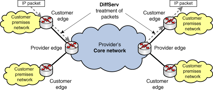
[Figure 2.17](https://learning.oreilly.com/library/view/qos-for-fixed/9781119470502/c02.xhtml#R_c02-fig-0017) Basic model for a single provider.
### 2.10.2 Basic DiffServ Inter‐Provider Model
In this section the DiffServ model is extended to a simple inter‐provider scenario, as shown in Figure [2.18](https://learning.oreilly.com/library/view/qos-for-fixed/9781119470502/c02.xhtml#c02-fig-0018). In general, there can be multiple network providers on the path of the user information transfer between two endpoints (two CEs). However, the simple inter‐provider scenario is to have just two providers in the path between the two sites of each customer, which are interconnected via (as a typical example) an IPX.
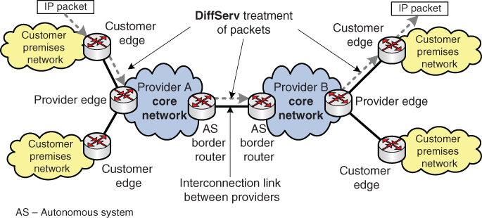
[Figure 2.18](https://learning.oreilly.com/library/view/qos-for-fixed/9781119470502/c02.xhtml#R_c02-fig-0018) Basic inter‐provider model.
With the aim of providing end‐to‐end QoS for the given connection, packets from the end‐users should be correctly marked on the inter‐provider link and avoid modifications of packets. The two providers, A and B, should have a peering agreement for an end‐to‐end service with the appropriate QoS mechanism applied on their interconnection. Also, when there is a need for monitoring of the customer (of either of the two providers in this scenario), such action is likely to involve both providers.
Which solution can be used for the interconnection between two network providers? Well, the interconnection should be possible with MPLS VPN [[34]](https://learning.oreilly.com/library/view/qos-for-fixed/9781119470502/c02.xhtml#c02-bib-0034), with a simple IP interconnection (with differentiation on the network layer, e.g. by using DiffServ fields in the IP headers), as well as with a layer 2 interconnection.
In general, in Internet networking philosophy, each of the networks which is a separate administrative domain (consisting of one or more ASs) is completely autonomous to choose traffic management mechanisms and QoS techniques, including the number of classes used inside the network provider's administrative domain. So, it is possible for one provider to group (aggregate) the traffic in three classes only (as an example), while the other operator may distinguish among five or six (or more) classes. However, at the interconnection point between the network providers there is a need to map classes which are being used by one provider to classes which are being used by the other provider and vice versa. This is usually implemented at the edge routers of each of the network providers.
## 2.11 IP Network Architectures for End‐to‐End QoS
There is a fundamental difficulty in the IP‐based platforms and networks due to heterogeneity in all aspects, including network infrastructures, type of applications and services carried through the network, management infrastructure, and end‐user devices. Simple use of IP as a transport technology does not mean networks and platforms are the same or even compatible. So, QoS is not assured by itself in IP networks, especially for traffic being transported through multiple network providers. There is an excessive number of different configurations among different networks, although all of them are using IP (and Internet networking principles) as a transport means. Thus it is hard to provide certain QoS for different services from one end to the other, simply because each network has different mechanisms and the levels of control and provision are also different. For example, as shown in Figure [2.19](https://learning.oreilly.com/library/view/qos-for-fixed/9781119470502/c02.xhtml#c02-fig-0019), one network provider may use an IntServ‐based approach, another one on the packets' route may use the DiffServ approach for QoS provisioning, a third one may use MPLS traffic engineering, while a fourth may use over‐provisioning (without explicit QoS support for given traffic types).
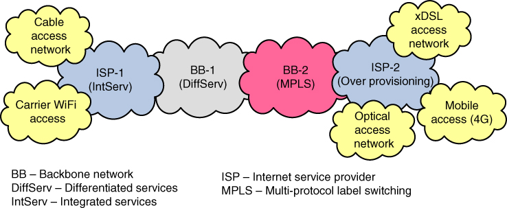
[Figure 2.19](https://learning.oreilly.com/library/view/qos-for-fixed/9781119470502/c02.xhtml#R_c02-fig-0019) IP networks with heterogeneous QoS mechanisms.
Possible mapping between DiffServ layer 3 marking, MPLS class of services, and Ethernet priority code points (for Ethernet versions which support it) is shown in Table [2.4](https://learning.oreilly.com/library/view/qos-for-fixed/9781119470502/c02.xhtml#c02-tbl-0004) [[39]](https://learning.oreilly.com/library/view/qos-for-fixed/9781119470502/c02.xhtml#c02-bib-0039).
[Table 2.4](https://learning.oreilly.com/library/view/qos-for-fixed/9781119470502/c02.xhtml#R_c02-tbl-0004) Mapping between DiffServ, MPLS, and Ethernet.
|Packet network QoS class|Description|Layer 3 packet marking: DSCP (DiffServ code point)|Layer 2 packet marking| ||
|---|---|---|---|---|---|
||||MPLS (class of service)|Ethernet (priority code point)|Applications|
|---|---|---|---|---|---|
|Classes 0, 1|Jitter sensitive|EF (expedited forward)|5|5 (default) or 6|Telephony|
|Classes 2, 3, 4|Low latency|AF (assured forward)|4, 3 or 2|4, 3 or 2|Signaling, interactive data|
|Class 5|Best efforts|DF (default forward)|0|0|Web browsing, email|
The basic network model (as given in the previous subsection) should be applied commonly to the providers, but the detailed QoS technologies to compose such a network model would be different for different providers and countries. Additionally, there are differences in the regulation environment, which is a fundamental framework for provision of QoS and QoE.
## 2.12 Discussion
Internet QoS was a very important topic in the 1990s when the two main IETF standards on QoS were developed, IntServ and DiffServ. They are not widely deployed today exactly as standardized, yet their concepts are still alive.
Internet capacity exploded in the 2000s with the spread of broadband access networks to residential users, via either fixed access (e.g. x digital subscriber line [xDSL] technologies over twisted pair copper lines, cable access, or fiber access) or mobile access (e.g. 3G, 4G, 5G mobile access networks). When there is a lot of capacity (although one should note that “a lot” is a relative term which refers only to a given point in time), packets are dropped only when capacity is reached. Then, QoS solutions can be very useful when capacity is saturated.
With the expansion of the Internet in the 2000s, a huge number of fiber links have been deployed, which give a lot of network capacity. Then, when there is lots of spare capacity, there is less requirement for Internet QoS end‐to‐end. However, carrier‐grade VoIP and IPTV, as well as VPNs as a replacement for leased lines for business users, require QoS support end‐to‐end because Internet traffic is unpredictable (bursty by nature, with a high degree of self‐similarity [[40]](https://learning.oreilly.com/library/view/qos-for-fixed/9781119470502/c02.xhtml#c02-bib-0040)). In short, IP‐based networks cannot be planned in the same manner as PSTNs, which were developed for a single ToS, the voice (i.e. telephony).
Additionally, emerging cloud computing and the Internet of Things may need certain QoS guarantees for specific types of users (business users, industry, etc.). Also, there is a need to guarantee QoS for access to the Internet as a whole. That is not access to particular applications over open Internet access (a particular application can be the Web, Skype, Viber, a social networking application, P2P applications such as BitTorrent, etc.) but to Internet access as a service provided by telecom operators (as ISPs) and used by end‐users to access all applications and services available through the public Internet network.
IP does not provide QoS mechanisms, but it has defined the ToS field in IPv4 and the DSCP field in IPv6 to specify QoS requirements on precedence, delay, throughput, and reliability, or to provide traffic differentiation. Overall, Internet architecture influences the QoS provisioning end‐to‐end. ASs are autonomous in every aspect regarding applied routing protocols and traffic management; only inter‐AS routing is standardized to go with a single routing protocol (that is BGP‐4).
Which is the default (and native) QoS in Internet? Well, the default QoS approach is the best‐effort approach (i.e. no QoS). That means every IP network gives its best‐effort to transfer every IP packet that travels through it, however that is done, without any guarantees about whether the packet will reach its destination and what will be the quality parameters associated with it (such as delay, losses). To introduce QoS in what was initially a no‐QoS Internet, the framework included IntServ (as the oldest), DiffServ (most used as a concept), and MPLS‐TE (the most used approach for QoS provisioning in transport IP networks) [[41]](https://learning.oreilly.com/library/view/qos-for-fixed/9781119470502/c02.xhtml#c02-bib-0041). Nevertheless, other proprietary vendor solutions (e.g. DPI) for Internet QoS are also being deployed in some IP networks.
## References
1. 1 RFC 791, Internet Protocol, IETF, September 1981.
2. 2 RFC 2460, Internet Protocol, Version 6 (IPv6), December 1998.
3. 3 RFC 768, User Datagram Protocol, August 1980.
4. 4 RFC 793, Transmission Control Protocol, September 1981.
5. 5 RFC 4960, Stream Control Transmission Protocol, September 2007.
6. 6 RFC 4340, Datagram Congestion Control Protocol (DCCP), March 2006.
7. 7 RFC 5944, IP Mobility Support for IPv4, Revised, November 2010.
8. 8 RFC 6275, Mobility Support in IPv6, July 2011.
9. 9 RFC 2581, TCP Slow Start, Congestion Avoidance, Fast Retransmit, and Fast Recovery Algorithms, January 1997.
10. 10 RFC 5681, TCP Congestion Control, September 2009.
11. 11 RFC 3550, RTP: A Transport Protocol for Real‐Time Applications, IETF, July 2003.
12. 12 RFC 2131, Dynamic Host Configuration Protocol, IETF, March 1997.
13. 13 RFC 3315, Dynamic Host Configuration Protocol for IPv6 (DHCPv6), IETF, July 2003.
14. 14 ITU‐T Recommendation E.164, The International Public Telecommunication Numbering Plan, November 2010.
15. 15 RFC 1035, Domain Names – Implementation and Specification, November 1987.
16. 16 RFC 7766, DNS Transport over TCP – Implementation Requirements, IETF, March 2016.
17. 17 Janevski, T. (2015). Internet Technologies for Fixed and Mobile Networks. Norwood, MA: Artech House.
18. 18 RFC 2616, Hypertext Transfer Protocol – HTTP/1.1, IETF, June 1999.
19. 19 RFC 7540, Hypertext Transfer Protocol Version 2 (HTTP/2), IETF, May 2015.
20. 20 Janevski, T. (2014). NGN Architectures, Protocols and Services. Chichester: Wiley.
21. 21 [http://bgp.potaroo.net](http://bgp.potaroo.net/), BGP Routing Table Analysis Reports, accessed in November 2017.
22. 22 Massachusetts Institute of Technology, Department of Electrical Engineering and Computer Science, Wide‐Area Internet Routing, January 2009.
23. 23 ITU‐T Recommendation G.114, One‐Way Transmission Time, May 2003.
24. 24 Ofcom UK, Traffic Management and Quality of Experience, 2011.
25. 25 RFC 1633, Integrated Services in the Internet Architecture: An Overview, June 1994.
26. 26 RFC 2474, Definition of the Differentiated Services Field (DS Field) in the IPv4 and IPv6 Headers, IETF, December 1998.
27. 27 RFC 3031, Multiprotocol Label Switching Architecture, IETF January 2001.
28. 28 ITU‐T Recommendation Y.1291, An Architectural Framework for Support of Quality of Service in Packet Networks, May 2004.
29. 29 RFC 2205, Resource ReSerVation Protocol (RSVP), IETF, September 1997.
30. 30 RFC 2475, An Architecture for Differentiated Services, IETF, 1998.
31. 31 RFC 3209, RSVP‐TE: Extensions to RSVP for LSP Tunnels, IETF, December 2001.
32. 32 RFC 3212, Constraint‐Based LSP Setup Using LDP, IETF, January 2002.
33. 33 RFC 4124, Protocol Extensions for Support of DiffServ‐aware MPLS Traffic Engineering, IETF, June 2005.
34. 34 RFC 4364, BGP/MPLS IP Virtual Private Networks (VPNs), IETF, February 2006.
35. 35 ITU‐T Recommendation Y.2770, Requirements For Deep Packet Inspection In Next Generation Networks, November 2012.
36. 36 RFC 5102, Information Model for IP Flow Information Export, IETF, January 2008.
37. 37 ITU‐T Recommendation Y.2771, Framework for Deep Packet Inspection, July 2014.
38. 38 ITU‐T Supplement 8 to E.800 series, Guidelines for Inter‐provider Quality of Service, November 2009.
39. 39 ITU‐T Recommendation Y.1545, Roadmap for the Quality of Service of Interconnected Networks That Use the Internet Protocol, May 2013.
40. 40 Janevski, T. (2003). Traffic Analysis and Design of Wireless IP Networks. Norwood, MA: Artech House.
41. 41 ITU‐T Technical Paper, How to Increase QoS/QoE of IP‐based Platform(s) to Regionally Agreed Standards, March 2013.
table of contents
search
Settings
[1 Introduction](https://learning.oreilly.com/library/view/qos-for-fixed/9781119470502/c01.xhtml)
2 Internet QoS
queue
QoS for Fixed and Mobile Ultra-Broadband
[3 QoS in NGN and Future Networks](https://learning.oreilly.com/library/view/qos-for-fixed/9781119470502/c03.xhtml)